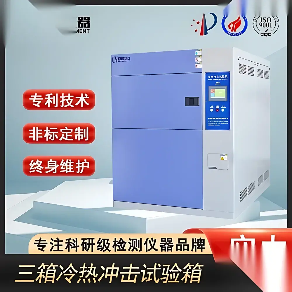
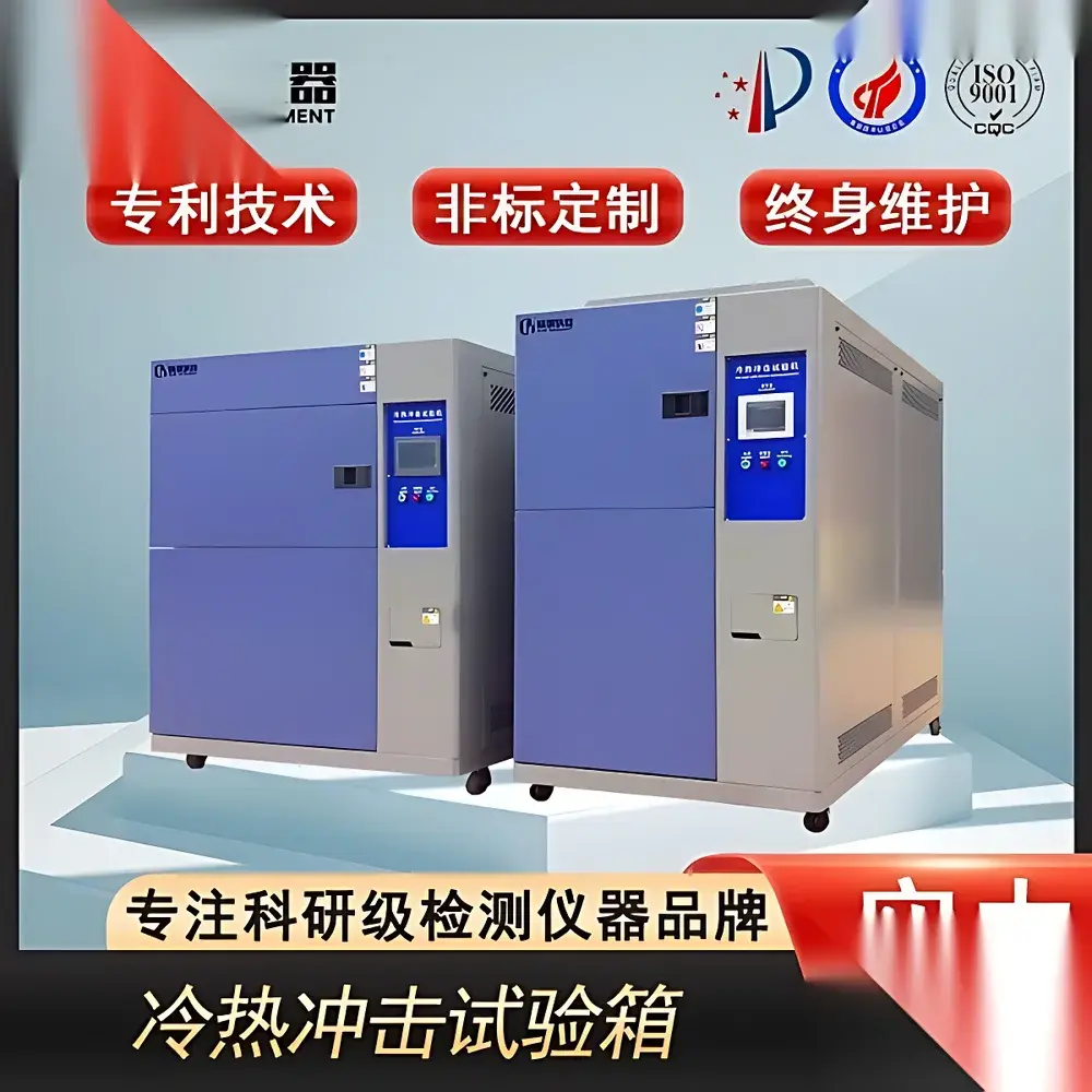
Thermal Shock Test Chamber – High-Low Temperature Cycling System
| Brand | OEM / Custom-Built |
|---|---|
| Origin | Imported |
| Manufacturer Type | Authorized Distributor |
| Price | USD 11,200 (FOB) |
| Compliance | MIL-STD-810G, GJB 150.3A–2009 (High Temp), GJB 150.4A–2009 (Low Temp), IEC 60068-2-14 |
Overview
The Thermal Shock Test Chamber – High-Low Temperature Cycling System is an engineered environmental test solution designed to evaluate material and component reliability under rapid, repetitive transitions between extreme high and low temperature extremes. Based on the principle of two-zone or three-zone thermal shock (depending on configuration), the system physically separates hot and cold chambers—typically maintained at +150 °C and −70 °C respectively—with a transfer mechanism (e.g., elevator or rotary basket) that moves test specimens between zones in ≤10 seconds. This enables controlled thermal stress application per ISO 16750-4, JEDEC JESD22-A104, and MIL-STD-810G Method 503.5. Unlike standard temperature cycling chambers, this system delivers high ΔT/Δt rates (>15 °C/s typical specimen surface transition), making it suitable for detecting latent defects such as solder joint fatigue, delamination in multilayer PCBs, seal integrity failure, and coefficient-of-thermal-expansion (CTE) mismatch in heterogeneous assemblies.
Key Features
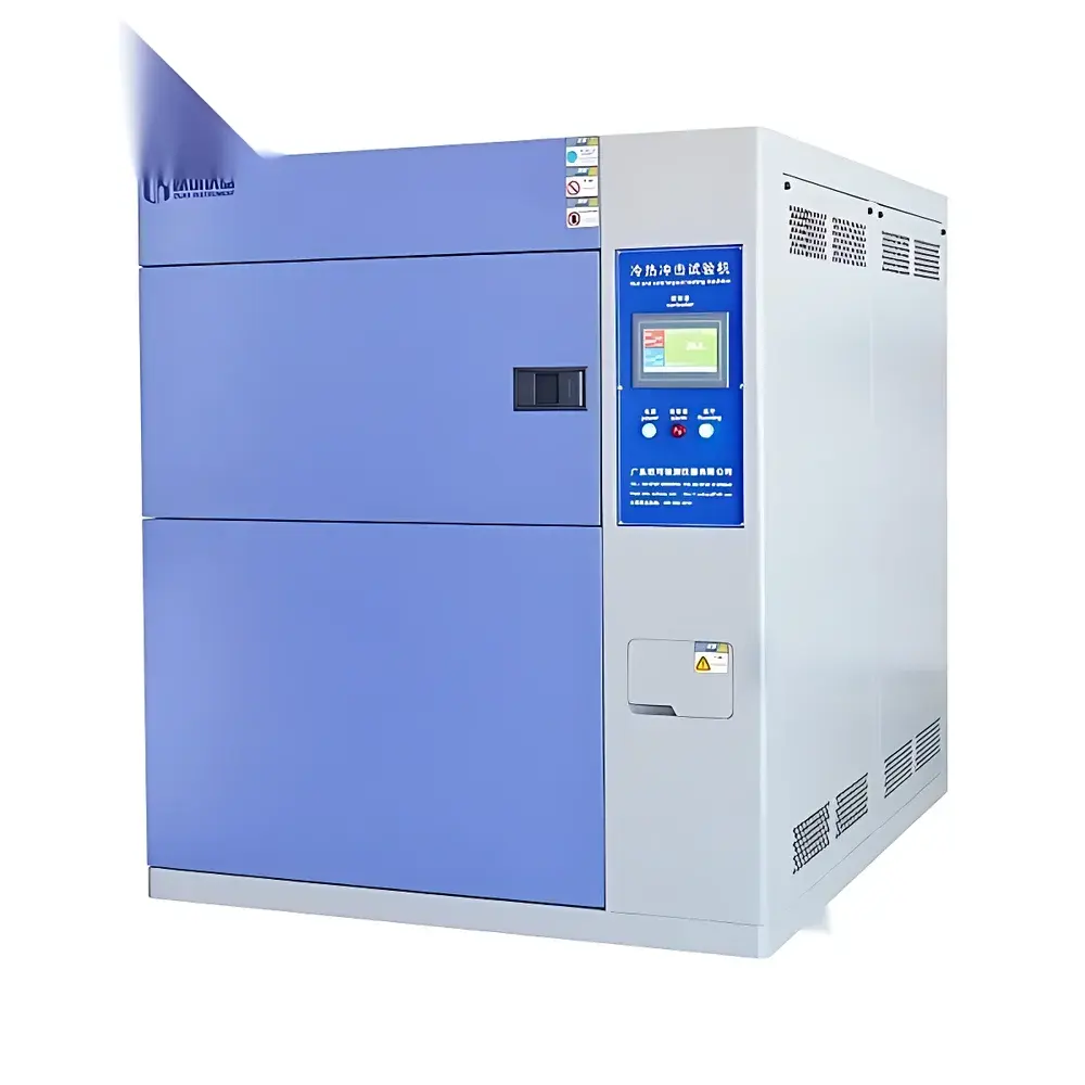
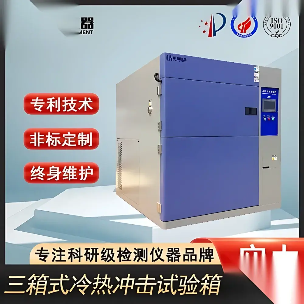
- Two- or three-chamber architecture with independent high-temperature (+150 °C max) and low-temperature (−70 °C min) zones, each equipped with dedicated Ni-Cr alloy heating elements and cascade refrigeration systems
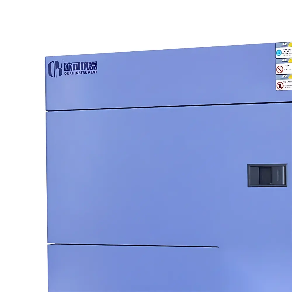
- Stainless steel 304 interior chamber with mirror-finish surface and SUS304 exterior housing featuring brushed matte finish for corrosion resistance and cleanroom-compatible aesthetics
- 100 mm-thick composite insulation: rigid polyurethane foam (PU) core + high-density glass fiber blanket, achieving thermal leakage <0.8 K/h under steady-state conditions
- Vertical-axis specimen transfer mechanism with pneumatic or servo-driven actuation; positional repeatability ±0.3 mm; dwell time programmable from 1 to 999 minutes per zone
- Dual-stage sealing system: high-tensile silicone gasket + secondary magnetic seal at chamber door interface, ensuring leak rate <1.0 × 10⁻³ mbar·L/s (He test)
- Multi-layer heated observation window with conductive ITO coating, enabling real-time visual monitoring without condensation or frost formation
- Standard 50 mm diameter test port (left-side mounted) with brass compression fitting, rated for vacuum compatibility and electrical feedthrough up to 300 VAC/10 A
- Redundant safety architecture: independent mechanical overtemperature cutoff (separate from main controller), phase-loss detection, refrigerant high-pressure cutout, and door-open interlock circuit
Sample Compatibility & Compliance
The chamber accommodates samples up to 500 mm × 500 mm × 500 mm (W×D×H) and supports both bare components and fully assembled units—including automotive ECUs, avionics modules, power semiconductor packages, and hermetically sealed sensors. It meets mandatory requirements for qualification testing under GJB 150.3A (high-temperature exposure), GJB 150.4A (low-temperature exposure), and GJB 150.5A (temperature shock). Optional configurations support humidity coupling (per IEC 60068-2-30) and vibration overlay (via integration with electrodynamic shakers). All control firmware and data logs comply with GLP/GMP traceability standards, including electronic signature capability and audit trail generation per FDA 21 CFR Part 11 when paired with validated software.
Software & Data Management
Equipped with a 10.1″ capacitive touchscreen HMI running embedded Linux, the system supports up to 120 stored test programs, each containing up to 1,200 programmable segments. Segments may be nested, looped (up to 9999 cycles × 999 sub-cycles), or conditionally branched based on real-time sensor feedback. PID+SSR/SCR dual-directional temperature control incorporates slope limiting logic to prevent overshoot during ramp transitions. RS-232 and RS-485 interfaces enable multi-unit daisy-chaining and centralized supervision via LabVIEW, MATLAB, or custom SCADA platforms. Export formats include CSV (time-stamped Thot, Tcold, Tspecimen, status flags) and PDF test reports with digital signature embedding.
Applications
This thermal shock system is routinely deployed in R&D validation labs, automotive Tier-1 supplier QC departments, and military/aerospace prime contractor test facilities. Typical use cases include: accelerated life testing of SiC/GaN power modules; screening for popcorning in plastic-encapsulated microcircuits (JEDEC J-STD-020); qualification of battery management systems (BMS) under extreme ambient gradients; verification of optical sensor housing integrity across −40 °C to +85 °C boundaries; and failure mode analysis of MEMS packaging subjected to repeated thermal transients.
FAQ
What is the minimum achievable transition time between temperature extremes?
Typical specimen transfer time is ≤8 seconds between chambers; actual thermal shock response depends on mass, geometry, and thermal diffusivity—verified via thermocouple mapping per IEC 60068-2-14 Annex B.
Can the system operate in non-shock modes (e.g., static high-temp soak only)?
Yes—each chamber functions independently as a standalone thermal chamber, supporting steady-state operation, linear ramping, and dwell-only profiles.
Is remote monitoring and alarm notification supported?
Standard Ethernet port enables SNMP-based network alerts; optional MQTT/OPC UA gateway available for IIoT platform integration.
What calibration documentation is provided upon delivery?
NIST-traceable certificate for all Class A PT100 sensors, including as-found/as-left data, uncertainty budget, and ISO/IEC 17025-compliant lab accreditation statement.
Are custom chamber dimensions or extended temperature ranges available?
Yes—engineering team supports bespoke configurations, including −80 °C low-end, +200 °C high-end, or large-volume chambers (up to 1 m³), subject to refrigeration and structural validation.
")


