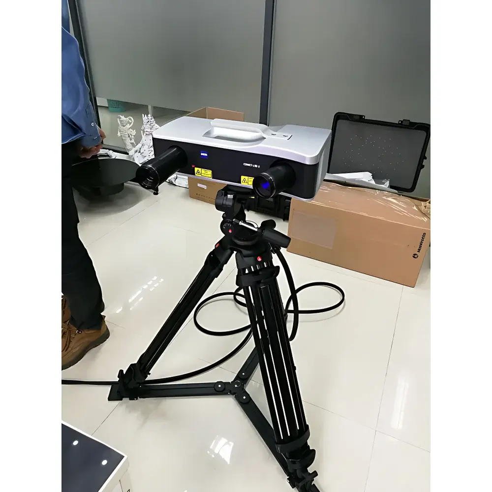
ZEISS COMET L3D Blue-Light 3D Scanning System for Industrial Metrology and Reverse Engineering
| Brand | ZEISS |
|---|---|
| Origin | Germany |
| Manufacturer Type | Authorized Distributor |
| Origin Category | Imported |
| Model | COMET L3D |
| Pricing | Available Upon Request |
| Measurement Principle | Structured Light Triangulation (Blue LED) |
| Resolution | Up to 5 MP (2448 × 2050 px) |
| Point Distance | 50–250 µm (configurable by measurement volume) |
| Acquisition Time | 1.5–2 s per scan |
| Measurement Volumes | 100 mm³ / 200 mm³ / 400 mm³ variants |
| Software | COMETplus v8.x (Windows-based, multi-core optimized) |
| Automation Support | COMETrotary (single-axis motorized turntable, ≤30 kg), COMETdual rotary (dual-axis tilt+rotate, ≤20 kg) |
| Compliance | ISO 10360-7, VDI/VDE 2634 Part 2, supports GLP/GMP audit trails via optional reporting modules |
Overview
The ZEISS COMET L3D is a high-precision, non-contact blue-light 3D scanning system engineered for industrial metrology, reverse engineering, and dimensional validation. Based on structured light triangulation with narrow-band blue LED illumination, it delivers robust surface capture of complex geometries without mechanical deformation—critical for fragile artifacts, soft polymers, foam prototypes, or heritage objects. Unlike tactile CMMs or articulated arm scanners, the COMET L3D eliminates probe-induced uncertainty and contact pressure errors, enabling repeatable sub-100 µm point spacing across defined volumetric fields (100/200/400 mm³). Its optical architecture is calibrated to international photogrammetric and coordinate metrology standards, ensuring traceability to national measurement institutes when operated under controlled environmental conditions (ISO 22476-1 compliant setup).
Key Features
- Non-contact, high-speed acquisition: Captures up to 2 million 3D points in 1.5 seconds per frame using synchronized blue-light projection and dual 2M/5M CMOS cameras.
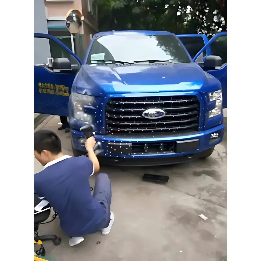
- Volumetric scalability: Three interchangeable measurement volumes (100/200/400 mm³) with corresponding point distances (50–250 µm), supporting both micro-detail scanning of jewelry and mid-size automotive components.
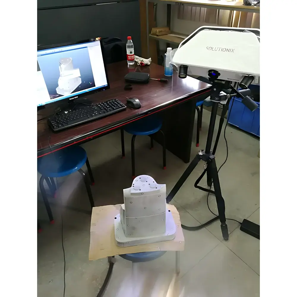
- Automated positioning integration: Fully software-synchronized with COMETrotary (single-axis, 30 kg capacity) and COMETdual rotary (dual-axis tilt + rotation, 20 kg capacity), enabling unattended multi-view alignment.
- Hardware-accelerated processing: COMETplus software leverages multi-threaded CPU architectures (up to 64 logical cores) and GPU-assisted mesh generation to produce clean, watertight STL files with minimal user intervention.
- Traceable calibration: Factory-certified according to VDI/VDE 2634 Part 2 (optical 3D measuring systems) and compatible with ISO 10360-7 verification protocols for volumetric accuracy assessment.
Sample Compatibility & Compliance
The COMET L3D accommodates a broad spectrum of material classes—including matte-finished metals, injection-molded thermoplastics, ceramic replicas, wax models, and aged organic substrates—without surface preparation or developer spray in most cases. Its blue-light wavelength minimizes ambient interference and avoids UV degradation risks associated with heritage conservation workflows. The system meets requirements for ISO/IEC 17025-accredited laboratories when deployed with documented calibration records, environmental monitoring (temperature ±1°C, humidity 40–60% RH), and operator competency validation. For regulated industries, optional COMETplus reporting modules support FDA 21 CFR Part 11-compliant electronic signatures, audit trails, and version-controlled data archiving.
Software & Data Management
COMETplus serves as the unified platform for acquisition, registration, mesh optimization, deviation analysis, and export. It supports hybrid measurement strategies—combining single-shot, multi-angle, and feature-guided alignment—enabling seamless integration with CAD comparison workflows (e.g., GD&T evaluation against nominal STEP or IGES models). Automated outlier rejection, adaptive smoothing filters, and curvature-aware decimation preserve geometric fidelity while reducing file size for downstream CAE use. All raw point clouds and processed meshes are stored in vendor-neutral formats (ASC, STL, PLY, OBJ), with metadata embedded per ISO 15926-2. Batch processing scripts and REST API endpoints allow integration into enterprise PLM and MES environments.
Applications
- Cultural heritage digitization: Contactless 3D documentation of archaeological finds, museum-grade sculptures, and archival restoration planning.
- Tooling & mold validation: CAV (Comparison Against CAD) analysis for injection molds, die-cast dies, and composite layup tools with full GD&T reporting (ISO 1101).
- Reverse engineering: Generation of parametric-ready surface models from legacy parts lacking original CAD, supporting rapid prototyping and functional redesign.
- Quality assurance in low-volume manufacturing: First-article inspection of aerospace brackets, medical device housings, and bespoke automotive trim components.
- Design iteration support: Real-time feedback loop between physical prototype scanning and topology-optimized CAD revisions.
FAQ
What surface finishes require spray coating prior to scanning?
Matte black, transparent, or highly reflective surfaces (e.g., polished stainless steel, glass) typically require a removable, sub-micron matte white spray (e.g., ZEISS ScanSpray) to ensure sufficient diffuse reflectance. Textured or diffusely scattering materials generally require no preparation.
Can the COMET L3D perform automated GD&T evaluation without external software?
Yes—COMETplus includes native GD&T modules compliant with ISO 1101 and ASME Y14.5, enabling position, flatness, cylindricity, and profile-of-a-surface evaluation directly against imported CAD references.
Is the system compatible with ISO 17025 accreditation requirements?
When operated within documented environmental controls, with annual traceable calibration certificates from ZEISS Service Centers, and with validated operator training records, the COMET L3D satisfies key metrological requirements of ISO/IEC 17025:2017 Clause 6.4 and 6.5.
How is measurement uncertainty quantified for a given scan?
Uncertainty budgets follow VDI/VDE 2634 Part 2 Annex C methodology, incorporating contributions from camera noise, projector stability, lens distortion, calibration target geometry, and environmental drift. Typical expanded uncertainties (k=2) range from ±8 µm (100 mm³ volume) to ±25 µm (400 mm³ volume) under laboratory conditions.
Does COMETplus support scripting for production-line integration?
Yes—Python-based automation interfaces (via COMETplus SDK) enable trigger synchronization with PLCs, robotic arms, and conveyor systems, supporting lights-out scanning cells in Industry 4.0 environments.