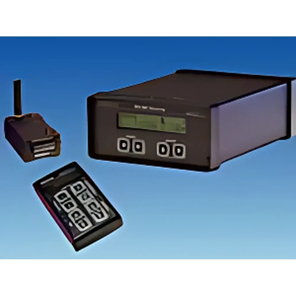
Binsfeld TT-10K Wireless Online Torque Telemetry System
| Brand | Binsfeld |
|---|---|
| Country of Origin | USA |
| Model | TT-10K |
| Max Torque Capacity | 10,000 N·m |
| Torque Measurement Range | 0–10,000 N·m |
| Torque Resolution | 1% of full scale |
| Torsional Angle Range | 0–360° |
| Motor Power Rating | 1 kW |
| Operating Temperature | −30 °C to +85 °C |
| RF Frequency Band | 902–925 MHz (16 programmable channels) |
| Transmission Distance | Up to 6 m (20 ft) |
| Sampling Bandwidth | DC to 500 Hz (−3 dB) |
| ADC Resolution | 14-bit |
| Transmitter Power Supply | 7.5–18 VDC, max 50 mA @ 350 Ω bridge |
| Battery Life | 24 h (9 V Li battery, 25 °C, 350 Ω bridge) |
| Centrifugal Acceleration Tolerance | 3000 g |
| Output Options | ±10 VDC analog (field-adjustable), RS-232 digital |
| Remote Control Range | 3 m (10 ft) |
Overview
The Binsfeld TT-10K Wireless Online Torque Telemetry System is a precision-engineered solution for non-intrusive, real-time torque and shaft power measurement on rotating machinery. Based on strain-gauge transduction and robust RF telemetry architecture, the system employs a full-bridge 350 Ω strain sensor bonded directly to the shaft surface—eliminating the need for mechanical coupling, slip rings, or shaft modification. Excited by a stable 2.5 VDC bridge voltage, the sensor outputs a low-level mV signal conditioned and digitized onboard the transmitter (TX10K-S), then wirelessly transmitted via a frequency-agile 902–925 MHz ISM band radio. With a DC–500 Hz bandwidth (−3 dB), 14-bit ADC resolution, and calibrated accuracy better than ±1% FS, the TT-10K delivers high-fidelity dynamic torque data under demanding industrial conditions—including extreme thermal gradients (−30 °C to +85 °C), high centrifugal loads (up to 3000 g), and electrically noisy environments. Its modular design supports both standalone torque monitoring and integrated shaft power calculation when paired with compatible rotational speed sensors such as the PLT-200 laser tachometer.
Key Features
- True wireless telemetry: No physical wiring between rotating and stationary components; eliminates slip ring wear, signal noise, and maintenance downtime.
- Programmable gain amplifier (500–16,000×): Enables flexible scaling of torque-to-voltage output without hardware changes—ideal for multi-range applications or post-installation calibration refinement.
- Remote configuration via handheld controller (RM10K): Adjust channel selection, gain, shunt calibration, and battery sleep mode from up to 3 meters away—no disassembly required.
- EMI-shielded transmitter housing with V-groove mounting strap: Ensures mechanical stability on shafts of any diameter and suppresses electromagnetic interference in heavy-industrial settings.
- Dual-output interface: Simultaneous ±10 VDC analog output (field-calibratable) and RS-232 serial digital output for integration with PLCs, DAQ systems, or SCADA platforms.
- Multi-system coexistence: Up to 16 independent TT-10K systems operate concurrently within the same facility using programmable RF channels—enabling synchronized multi-axis monitoring.
Sample Compatibility & Compliance
The TT-10K is compatible with solid or hollow metallic shafts of any diameter, provided surface preparation and strain gauge bonding follow ASTM E251 and ISO 14129 guidelines. It supports standard 350 Ω foil strain gauges and accommodates custom bridge configurations. The system meets FCC Part 15 Subpart C requirements for intentional radiators and complies with CE EMC Directive 2014/30/EU. For regulated environments—including those governed by FDA 21 CFR Part 11, ISO 9001, or GLP/GMP quality systems—the TT-10K supports audit-ready documentation of calibration events, gain settings, and firmware versions via its RS-232 interface and remote control log functionality. All hardware is rated IP54 for dust and moisture resistance during operation.
Software & Data Management
While the TT-10K operates autonomously without proprietary software, its RS-232 output is fully compatible with industry-standard data acquisition platforms including National Instruments LabVIEW, MATLAB Data Acquisition Toolbox, and Keysight PathWave. ASCII-formatted telemetry packets include timestamped torque values, RF signal strength, error codes, and system status flags—enabling traceable, time-synchronized analysis. When used with the PLT-200 laser tachometer, shaft power (kW) is computed in real time using the formula P = (2π × N × T)/60, where N is RPM and T is torque in N·m. Raw data files support CSV export for long-term trending, statistical process control (SPC), and failure mode analysis per ISO 13374.
Applications
- Marine propulsion systems: Continuous torque monitoring of main reduction gears and propeller shafts for condition-based maintenance and fuel efficiency optimization.
- Rolling mill drive trains: Real-time torsional stress assessment of motor-to-stand couplings to prevent catastrophic fatigue failures.
- Wind turbine drivetrains: Validation of gearbox input torque during grid-synchronization events and yaw misalignment diagnostics.
- Automotive powertrain testing: In-vehicle driveline torque mapping during NVH and durability campaigns.
- Paper machine calender stacks: Synchronized torque and speed profiling across multiple nip rolls to ensure uniform sheet caliper and gloss.
- Cranes and hoists: Overload detection and duty-cycle logging for compliance with OSHA 1910.179 and EN 13001 standards.
FAQ
Can the TT-10K measure static torque?
Yes—the system captures DC-coupled torque signals and maintains stability at zero rotation, enabling accurate static and quasi-static measurements.
Is recalibration required after changing gain settings?
No—gain is digitally applied post-conversion and does not affect sensor linearity; however, mechanical shunt calibration is recommended after any physical repositioning of the strain gauge assembly.
What is the maximum shaft rotational speed supported?
The transmitter is qualified for continuous operation up to 10,000 RPM; performance beyond this depends on mechanical balance and centrifugal loading of the bonded strain gauge.
Does the system support synchronization with external triggers or clocks?
RS-232 output includes embedded timestamps referenced to the transmitter’s internal oscillator; external TTL sync input is not available but can be implemented via third-party DAQ hardware.
How is traceability maintained for regulatory audits?
All configuration parameters (channel, gain, filter setting) are stored in non-volatile memory and retrievable via RS-232 command set; calibration certificates and installation records must be retained separately per ISO/IEC 17025 requirements.
")


