Lei-Tech LK-LSRT500-600 / LK-LSRT5000-1200 In-Situ High-Low Temperature Mechanical Tensile Testing System
| Brand | Lei-Tech |
|---|---|
| Origin | Tianjin, China |
| Manufacturer Type | Direct Manufacturer |
| Instrument Type | Electromechanical Tensile Tester |
| Max Test Load | 0.5 kN / 5 kN |
| Force Range | 0–500 N / 0–5000 N |
| Force Resolution | 0.1 N / 1 N |
| Stroke | 40 mm / 70 mm |
| Displacement Resolution | 1 µm / 10 µm |
Overview
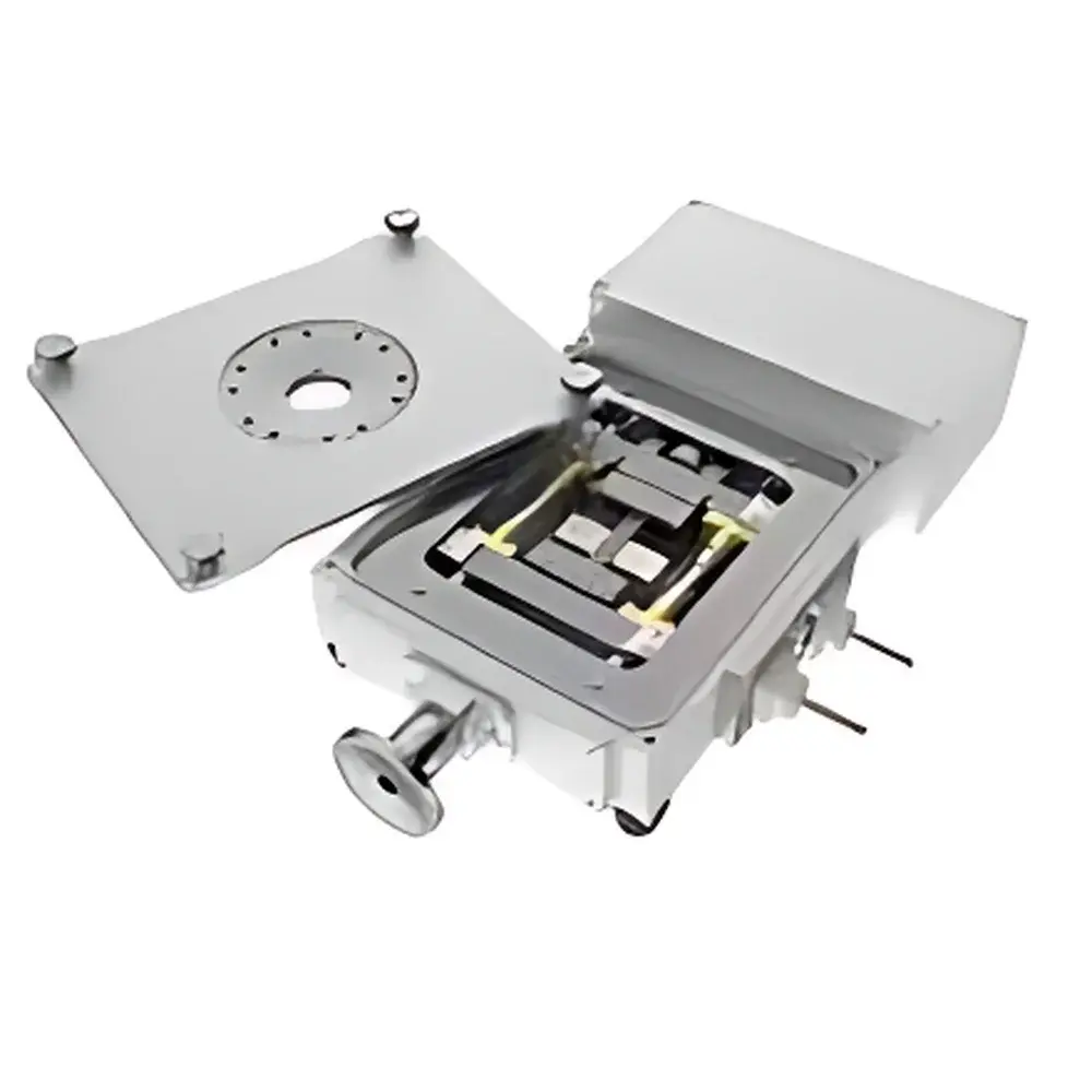
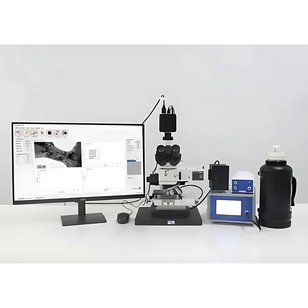
The Lei-Tech LK-LSRT500-600 and LK-LSRT5000-1200 In-Situ High-Low Temperature Mechanical Tensile Testing Systems are engineered for quantitative mechanical characterization of solid materials under controlled thermal environments while enabling real-time microscopic observation. These systems operate on a precision electromechanical actuation principle, utilizing closed-loop servo control to deliver calibrated tensile, compressive, and cyclic loading profiles. Designed specifically for integration with optical microscopes, scanning electron microscopes (SEM), and synchrotron beamlines, the platform supports true in-situ deformation studies—capturing microstructural evolution (e.g., crack initiation, grain boundary sliding, phase transformation, fiber pull-out) concurrently with mechanical response. The system accommodates temperature extremes from cryogenic conditions (down to –196 °C using liquid nitrogen cooling) to high-temperature regimes (up to 1200 °C via resistive heating elements), making it suitable for investigating thermomechanical coupling effects across polymer, metallic, ceramic, nanocomposite, and biomaterial systems.
Key Features
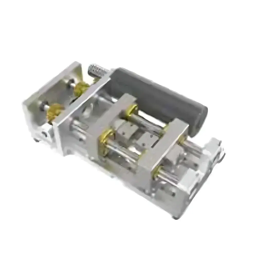
- Modular dual-platform design: LK-LSRT500-600 optimized for sub-gram samples and high-resolution displacement tracking (1 µm resolution); LK-LSRT5000-1200 configured for higher-load applications up to 5 kN with robust thermal shielding and extended stroke (70 mm)
- Thermally isolated chamber architecture with multi-zone temperature control—ensuring axial uniformity ±2 °C across the gauge length during ramping or isothermal holds
- Compact footprint (< 300 × 250 × 200 mm) enables seamless integration into SEM chambers (with compatible vacuum feedthroughs) and inverted optical microscope stages
- High-stiffness load frame with low-noise force transducers (calibrated traceable to NIST standards), delivering force accuracy within ±0.5% of reading over full scale
- Real-time synchronization of load/displacement data with external imaging systems via TTL triggers and analog voltage outputs (±10 V)
Sample Compatibility & Compliance
The system accepts standardized tensile specimens (ASTM E8/E21, ISO 6892-1) as well as custom geometries—including thin films, fibers, micro-pillars, and MEMS-scale devices—via interchangeable grips (pneumatic, wedge, pin, and collet types). All thermal modules comply with IEC 61000-4 electromagnetic compatibility requirements. Force calibration procedures follow ISO 7500-1 Class 0.5 guidelines. For regulated environments, the software supports audit trails, user access levels, and electronic signatures compliant with FDA 21 CFR Part 11 when deployed with validated configurations. Documentation includes full traceability to national metrology institutes and conforms to GLP/GMP laboratory quality management expectations.
Software & Data Management
Control and analysis are performed via Lei-Tech’s proprietary TensileStudio™ software suite, built on a deterministic real-time kernel (Windows OS, 64-bit). The interface provides synchronized acquisition of force, displacement, temperature, and external image timestamps at up to 1 kHz sampling rate. Data export formats include CSV, HDF5, and MATLAB .mat—enabling direct import into finite element post-processing tools (e.g., ABAQUS, ANSYS). Scriptable test protocols support automated thermal-mechanical cycles (e.g., “hold at 800 °C → apply 0.1 mm/min strain → hold → cool at 5 °C/min”), with configurable safety interlocks (overload cutoff, thermal runaway shutdown, vacuum loss detection). Raw datasets retain full metadata: operator ID, instrument serial number, calibration certificate IDs, and environmental log files.
Applications
- Creep and stress-relaxation behavior of thermoplastics and shape-memory alloys across glass transition and melting regimes
- In-situ SEM observation of dislocation dynamics and void coalescence in Ti-6Al-4V during high-temperature tensile loading
- Interfacial debonding kinetics in carbon-fiber/epoxy composites under thermal cycling
- Mechanical hysteresis and fatigue threshold mapping of piezoelectric ceramics at elevated temperatures
- Strain-dependent phase evolution in VO₂ thin films monitored via simultaneous Raman spectroscopy and load control
FAQ
What vacuum compatibility options are available for SEM integration?
Standard configurations support ≤10⁻³ Pa base pressure; optional differential pumping stages and ceramic feedthroughs enable operation down to 10⁻⁶ Pa.
Can the system perform dynamic mechanical analysis (DMA)?
Yes—when paired with optional harmonic excitation module (±500 µm amplitude, 0.01–50 Hz), it supports isothermal and temperature-ramped DMA per ASTM D7028.
Is third-party software control supported?
Yes—LabVIEW, Python (PyVISA), and MATLAB APIs are provided with full command reference documentation and example scripts.
How is thermal gradient minimized across the specimen gauge length?
By combining radial insulation layers, axial heat-sink design, and active PID-controlled end-block compensation—achieving < ±3 °C gradient over 2 mm gauge lengths at 1000 °C.
What maintenance intervals are recommended for long-term force accuracy?
Annual recalibration of load cells and displacement encoders is advised; thermal sensor verification every six months per ISO/IEC 17025 internal checklist.


