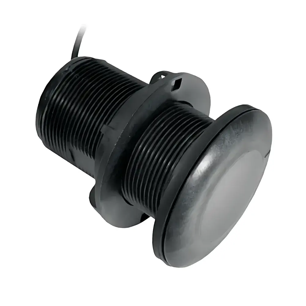
Airmar P19 High-Frequency Through-Hull Depth Sounder
| Brand | Airmar |
|---|---|
| Origin | USA |
| Model | P19 |
| Frequency | 200 kHz |
| Beamwidth | 11° @ 200 kHz |
| Output Power | 375 W |
| Maximum Depth Range | 206 m |
| Housing Material | Plastic or Bronze (optional) |
| Mounting Type | Through-hull |
| Transducer Window | Polyurethane |
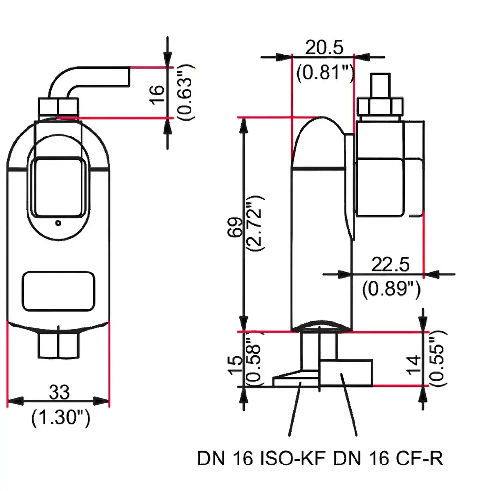
| Hull Penetration | 5 mm (3/16") |
| Installation Hole Diameter | 51 mm |
| Stub Length | 94 mm |
| Cable Length | 10 m |
| Weight | 0.5 kg |
| Hull Deadrise Compatibility | 0°–24° (three fixed tilt options: 0°, 12°, 20°) |
| Temperature Sensor | Optional |
| Compliance | ABYC H-27 |
Overview
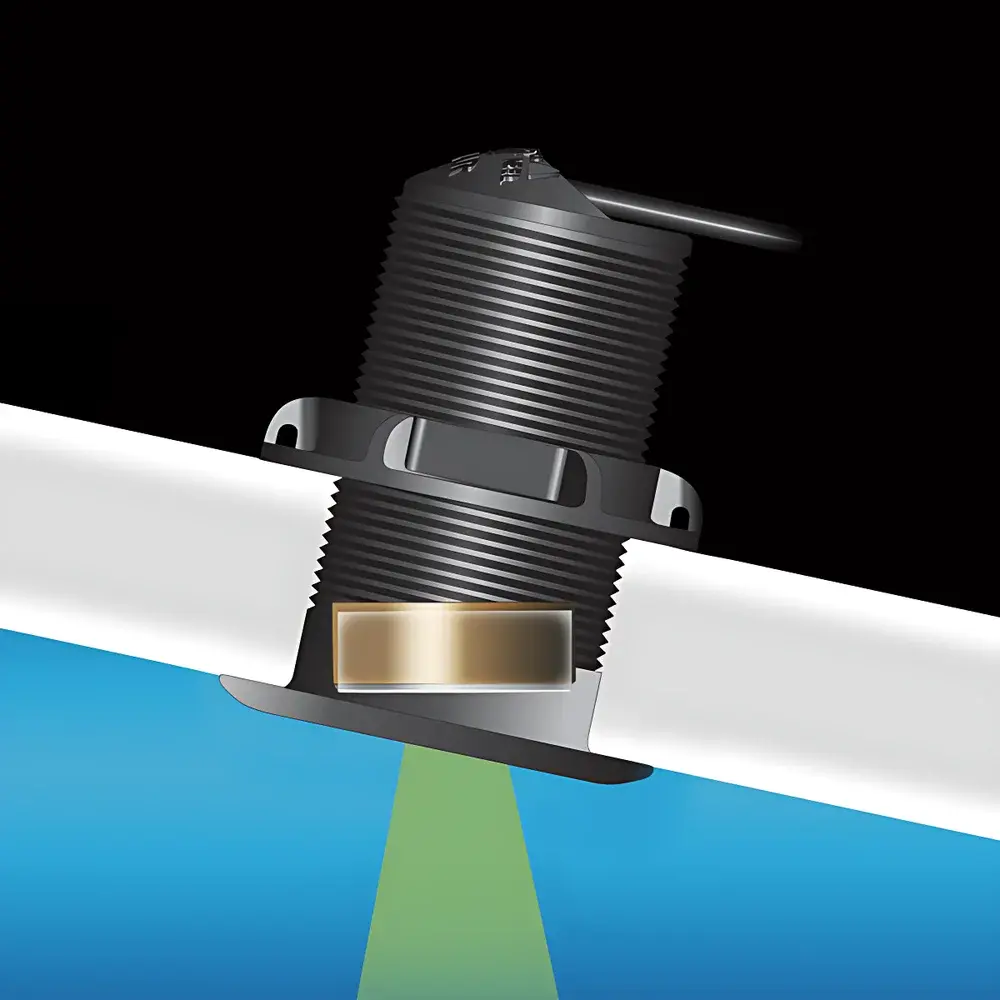
The Airmar P19 is a high-frequency, through-hull depth sounder engineered for precision hydrographic measurement in small to mid-sized recreational and commercial vessels up to 9 meters in length. Operating at 200 kHz, the P19 leverages narrow-beam acoustic propagation (11° beamwidth) to deliver high-resolution bathymetric data with minimal side-lobe interference. Its core transduction principle relies on piezoelectric ceramic elements arranged in a patented Tilted™ configuration—where the active ceramic is physically angled within the housing to compensate for hull deadrise without requiring external fairings or flow deflectors. This internal mechanical tilt enables true vertical beam projection even when mounted on inclined hulls, significantly improving echo return consistency and depth measurement reproducibility across dynamic sea states. Designed for low-drag integration, the P19 extends only 5 mm beyond the hull surface, reducing hydrodynamic resistance and minimizing cavitation risk at planing speeds.
Key Features
- Fixed-tilt ceramic element architecture: Available in three calibrated versions—0° (for flat or near-flat hulls, 0°–7° deadrise), 12° (8°–15° deadrise), and 20° (16°–24° deadrise)—ensuring optimal beam alignment without field adjustment.
- Through-hull mounting with integrated polyurethane acoustic window: Provides robust pressure sealing and acoustic impedance matching for efficient energy transfer into water.
- ABYC H-27-compliant housing: Certified for marine electrical safety, corrosion resistance, and mechanical integrity under cyclic pressure and thermal stress.
- Optional integrated temperature sensor: Enables simultaneous water temperature acquisition for real-time sound velocity correction, critical for depth accuracy in variable salinity or thermal stratification conditions.
- Dual-material housing option: Standard plastic housing for cost-sensitive applications; optional bronze housing for enhanced durability and galvanic compatibility in saltwater environments.
- Compact stub design (94 mm length) and minimal external profile (5 mm protrusion): Facilitates installation in constrained bilge spaces and reduces drag-induced noise during high-speed operation.
Sample Compatibility & Compliance
The P19 is validated for use on fiberglass, aluminum, and wood hulls with deadrise angles between 0° and 24°. Its polyurethane acoustic window ensures stable coupling across heterogeneous hull materials without requiring specialized coupling compounds. The transducer meets ABYC H-27 requirements for underwater electrical safety, grounding continuity, and pressure-rated sealing performance up to 10 m static head. While not certified for Class I Div 1 hazardous locations, it complies with CE marking directives for electromagnetic compatibility (EMC Directive 2014/30/EU) and low-voltage equipment (LVD Directive 2014/35/EU). It is compatible with NMEA 0183 v3.0 and NMEA 2000 networks via standard interface modules from Garmin, Lowrance, and Raymarine.
Software & Data Management
The P19 operates as a sensor-level device and does not include embedded firmware or onboard data logging. All signal processing, depth calculation, and temperature compensation are performed by the host chartplotter or multifunction display (MFD). When connected to NMEA 2000 networks, depth and optional temperature data are transmitted using standardized PGNs (e.g., PGN 127250 – Depth, PGN 130311 – Environmental Parameters). No proprietary drivers or configuration utilities are required. For regulatory traceability in survey or fisheries monitoring contexts, raw analog output (if enabled via compatible MFD) may be recorded alongside vessel position (GPS) and time stamps for post-processing in GIS or hydrographic analysis software compliant with IHO S-44 standards.
Applications
- Recreational navigation: Real-time depth monitoring for safe shallow-water passage, anchoring, and submerged obstacle avoidance.
- Small-craft hydrographic surveys: Bathymetric profiling of inland lakes, rivers, and coastal zones where high spatial resolution is prioritized over ultra-deep range.
- Fisheries support: Detection of bottom contours, thermocline layers (when paired with temperature sensor), and potential fish aggregation zones via echo intensity analysis.
- Marine research platforms: Integration into autonomous surface vehicles (ASVs) or remotely operated towed bodies requiring low-profile, low-power sonar sources.
- Vessel performance optimization: Correlation of draft, trim, and speed with real-time depth data to refine hull resistance modeling.
FAQ
Does the P19 require an external fairing or flow cone for proper operation?
No. The Tilted™ ceramic design eliminates the need for external hydrodynamic fairings by achieving vertical beam alignment internally.
Can the P19 be installed on metal hulls?
Yes—provided the hull thickness falls within the specified mounting range and proper isolation gaskets (included) are used to prevent galvanic corrosion.
Is the temperature sensor field-installable after purchase?
No. The temperature sensor must be selected at time of order; it is integrated during manufacturing and cannot be retrofitted.
What is the maximum rated operating depth for the P19?
The transducer is pressure-rated for continuous operation at depths up to 206 meters, assuming full submersion and nominal water column sound velocity (1500 m/s).
How does hull deadrise affect beam geometry if the wrong tilt version is selected?
An incorrect tilt angle causes beam skew, resulting in reduced bottom return amplitude, increased multi-path reflections, and potential depth underestimation—particularly at higher speeds or in rolling conditions.