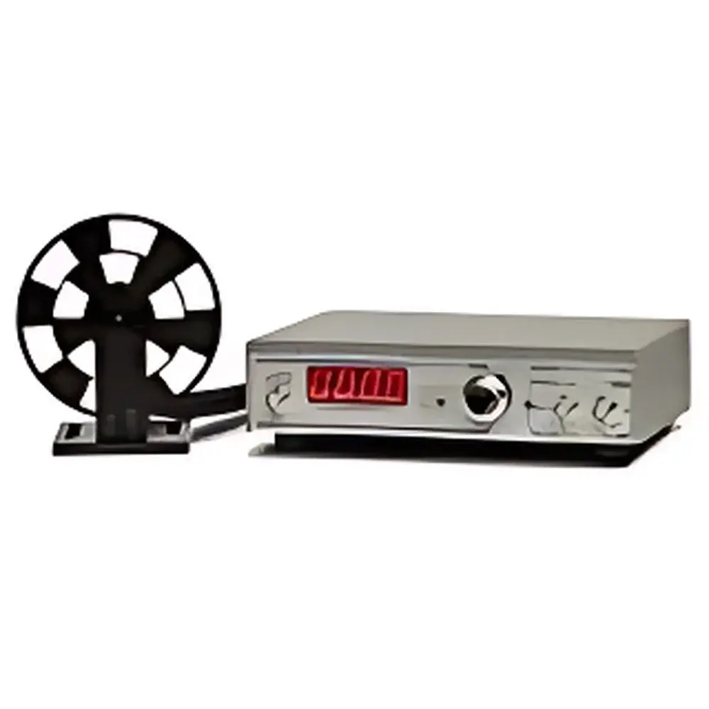
Stanford Research Systems SR540 Optical Chopper
| Brand | Stanford Research Systems |
|---|---|
| Model | SR540 |
| Type | Precision Synchronous Optical Chopper |
| Origin | USA |
| Blade Configurations | 5/6-slot (4–400 Hz), 25/30-slot (400–3700 Hz) |
| Frequency Stability | ±250 ppm/°C (typ.) |
| Phase Jitter | 0.2° rms (50–400 Hz), 0.5° rms (400–3700 Hz) |
| Frequency Resolution & Accuracy | 1 Hz (4-digit LED display) |
| Control Interface | 0–10 VDC analog input (0–100% full scale), manual 10-turn potentiometer with three decade ranges |
| Reference Outputs | Sum (Σ), Difference (Δ), Inner, Outer, 5×Outer |
| Mounting Options | Bolt clamp or 0.75" rod mount |
| Blade Diameter | 4.04" ±0.002" |
| Controller Dimensions (W×H×L) | 196 × 46 × 130 mm |
| Chopper Head Dimensions (W×H×L) | 71 × 53 × 25 mm |
| Cable Length | 1.83 m |
| Power Consumption | 12 W |
| Input Voltage | 100/120/220/240 VAC, 50/60 Hz |
| Warranty | 1 year parts & labor (excl. motor: 90 days) |
Overview
The Stanford Research Systems SR540 Optical Chopper is a high-stability, electronically synchronized chopper system engineered for precision modulation of continuous-wave light sources in demanding optical measurement applications. Based on a robust synchronous motor-driven rotating blade architecture, the SR540 employs phase-locked feedback control to maintain exceptional frequency accuracy and minimal phase jitter across its full operational range—from 4 Hz to 3.7 kHz. Its dual-blade design (5/6-slot and 25/30-slot interchangeable blades) enables optimized signal-to-noise ratio (SNR) and harmonic rejection in both low-frequency lock-in detection and high-speed photometric experiments. Unlike open-loop choppers, the SR540 integrates real-time frequency monitoring and analog voltage-controlled operation, ensuring traceable, repeatable modulation essential for quantitative spectroscopy, interferometry, and low-light photodetection setups compliant with ISO/IEC 17025 laboratory practices.
Key Features
- Wide, segmented frequency range: 4 Hz–400 Hz (5/6-slot blade) and 400 Hz–3.7 kHz (25/30-slot blade), supporting both slow thermal response measurements and fast photodiode-based detection.
- Low phase jitter performance: ≤0.2° rms (50–400 Hz) and ≤0.5° rms (400–3700 Hz), critical for maintaining lock-in amplifier reference integrity and minimizing demodulation error.
- Four-digit LED frequency display with 1 Hz resolution and calibrated accuracy—enabling direct readout without external frequency counters.
- Three-range manual frequency control via precision 10-turn potentiometer, supplemented by 0–10 VDC analog voltage input for remote or programmable setpoint override.
- Dedicated reference output channels: inner (blade hub), outer (perimeter), 5×outer (harmonic multiplication), sum (Σ), and difference (Δ)—facilitating dual-beam nulling, balanced detection, and common-mode noise rejection.
- Mechanically stable mounting: compatible with standard optical tables via bolt clamp or 0.75″ diameter kinematic rod mount; chopper head mass and inertia are minimized to reduce vibration coupling.
Sample Compatibility & Compliance
The SR540 is designed for integration into vacuum-compatible, EMI-controlled, and Class 1 laser environments. Its all-metal housing, grounded chassis, and shielded cabling meet FCC Part 15 Class B and CE electromagnetic compatibility requirements. While not a medical or industrial safety-certified device per se, its stable chopping profile supports experimental compliance with ASTM E131 (Standard Terminology Relating to Molecular Spectroscopy) and ISO 13406-2 (for modulated illumination in imaging metrology). The unit operates within standard laboratory ambient conditions (15–30 °C, <80% RH non-condensing) and exhibits thermal drift <2% over its specified frequency band—validated per manufacturer’s calibration protocol traceable to NIST standards. No optical coatings or transmission elements are integrated; users select appropriate reflective or transmissive blades based on wavelength (UV–IR) and power handling requirements.
Software & Data Management
The SR540 operates as a standalone analog instrument with no embedded firmware or USB/Ethernet interface. However, its 0–10 VDC control input and TTL-compatible reference outputs are fully interoperable with common lab automation platforms—including LabVIEW (via DAQmx), Python (PyVISA + GPIB/USB-GPIB adapters), and MATLAB Instrument Control Toolbox. Reference signals are electrically isolated and impedance-matched (50 Ω) for direct connection to lock-in amplifiers (e.g., SRS SR830, Zurich Instruments HF2LI) or digitizers (e.g., Keysight U1051A). Audit-ready configuration logging is achieved by recording analog control voltages and displayed frequencies alongside experimental metadata—a practice aligned with GLP documentation requirements for method validation reports.
Applications
- Lock-in amplification in FTIR, photoacoustic, and photothermal spectroscopy where precise reference timing reduces 1/f noise floor.
- Dual-beam absorption measurements requiring simultaneous Σ and Δ outputs for real-time baseline correction.
- Calibration of photodetector linearity and rise time using square-wave-modulated LEDs or lasers.
- Modulation transfer function (MTF) characterization of optical components and imaging systems.
- Time-resolved fluorescence lifetime measurements using gated detection synchronized to chopper phase.
- Null-balance experiments in ellipsometry and polarimetry where common-mode rejection exceeds 60 dB.
FAQ
What blade types are supported, and how do I select the correct one?
The SR540 accepts two blade families: 5/6-slot blades for low-frequency stability (4–400 Hz) and 25/30-slot blades for high-frequency operation (400–3700 Hz). Selection depends on required modulation depth, harmonic content, and detector bandwidth—not on wavelength. Blades are user-replaceable and mechanically keyed.
Is the SR540 compatible with vacuum or cleanroom environments?
The chopper head and controller are rated for ambient air operation only. Vacuum use requires custom feedthroughs and outgassing evaluation; contact SRS Application Engineering for material certifications (e.g., RoHS, REACH).
Can I synchronize multiple SR540 units?
Yes—via the outer reference output of one unit driving the 0–10 VDC input of another, or by using an external master clock fed into the reference input (requires optional sync adapter kit). Phase alignment accuracy is ±0.3° under matched temperature conditions.
Does the warranty cover motor replacement if failure occurs after 90 days?
Motor coverage is limited to 90 days from shipment. Extended service plans are available directly through Stanford Research Systems’ Technical Support Group upon request.
How is frequency stability affected by line voltage fluctuations?
The internal regulated power supply maintains frequency stability independent of ±10% AC line variation. No additional line conditioner is required for typical lab-grade power distribution.