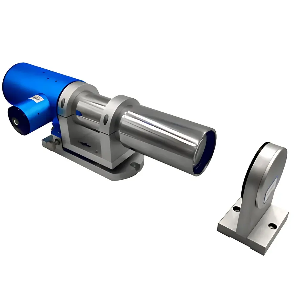
YANRUN YRMAT3615C Dual-Axis Photoelectric Autocollimator (0.3 arcsec)
| Brand | YANRUN |
|---|---|
| Origin | Shanghai, China |
| Manufacturer Type | Manufacturer |
| Model | YRMAT3615C |
| Measuring Distance | 0–15 m |
| Focal Length | 360 mm |
| Aperture | 38 mm |
| Resolution | Adjustable from 1.0 to 0.1 arcsec |
| Accuracy (Center) | ±0.3 arcsec (0–±100 arcsec), ±1 arcsec (0–±600 arcsec) |
| Field of View (X/Y) | 1400″ × 1200″ |
| Detector | High-Precision Photodetector |
| Light Source | Imported Semiconductor LED |
| Sampling Frequency | 30 Hz (typ.) |
| Interface | USB 2.0/3.0 |
| Dimensions | 450 × 155 × 125 mm |
| Weight | 4.3 kg |
| Software Platform | Windows 7 or later (64-bit), Intel Core i3-4th gen or higher, ≥2.3 GHz |
Overview
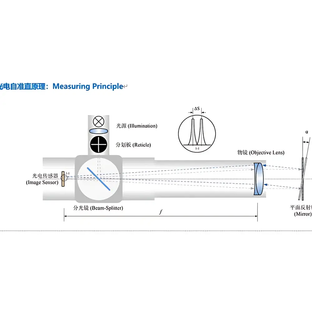
The YANRUN YRMAT3615C Dual-Axis Photoelectric Autocollimator is an advanced optical metrology instrument engineered for high-precision angular measurement based on the fundamental principle of optical autocollimation. It employs a collimated beam generated by a precision 360 mm focal length objective lens, directed onto a plane mirror placed at the measurement site. The reflected beam re-enters the objective and is focused onto a high-resolution photodetector array located at the shared focal plane—forming a co-focal optical architecture. When the mirror rotates by angle α, the returning image shifts by ΔS ≈ 2f·α (where f = 360 mm), enabling sub-arcsecond angular quantification via pixel-level displacement analysis. Unlike traditional visual autocollimators requiring subjective eyepiece alignment, the YRMAT3615C digitizes the entire measurement chain: illumination (long-life LED), imaging (1400″ × 1200″ FoV), signal acquisition (30 Hz real-time sampling), and computation—all synchronized through deterministic USB 2.0/3.0 communication with host PC. Designed for laboratory-grade repeatability and field-deployable robustness, it serves as a traceable, non-contact angular reference in environments demanding compliance with ISO 10110-5 (optical component testing), ISO 230-1 (machine tool geometric accuracy), and ASTM E2917 (angular displacement measurement standards).
Key Features
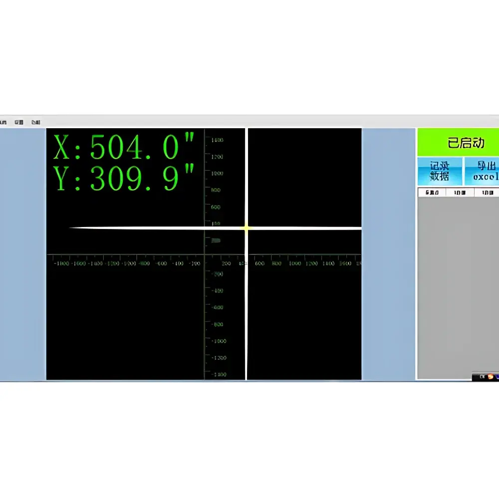
- Dual-axis simultaneous measurement (X and Y) with independent resolution adjustment (0.1–1.0 arcsec), eliminating sequential axis alignment delays.
- Real-time electronic reticle display with auto-trace curve generation and automatic error calculation per ISO 1101 geometric tolerancing conventions.
- High-stability semiconductor LED light source with >50,000-hour operational lifetime and minimal thermal drift—certified per IEC 62471 photobiological safety requirements.
- Integrated two-axis fine-adjustment base with micrometer-driven kinematic mounts, enabling sub-microradian tip/tilt control during setup.
- USB-powered modular architecture: no external power supply required for core operation; optional wireless data acquisition module supports touch-screen interface for remote deployment.
- Multi-language software interface (English, Chinese, Russian, Korean) compliant with ISO/IEC 17025 documentation requirements for calibration laboratories.
- Configurable measurement modes: single-point angular offset, continuous dynamic tracking, step-and-hold sequence logging, and multi-point spatial mapping.
Sample Compatibility & Compliance
The YRMAT3615C interfaces with standard optical flat mirrors (included), magnetic mirror mounts, adjustable prism platforms, and laser-assisted alignment accessories—enabling rapid adaptation across mechanical, optical, and aerospace test configurations. Its 15-meter maximum working distance accommodates large-scale machine tool verification (e.g., CNC gantry straightness per ISO 230-2), while its 0.3 arcsec center accuracy meets the stringent demands of national metrology institutes performing secondary standard calibrations. All firmware and software modules adhere to GLP/GMP audit trail requirements: every measurement session logs operator ID, timestamp, environmental metadata (ambient temperature/humidity if externally fed), and raw pixel displacement arrays. Data export formats include CSV, XML, and native Excel (.xlsx) with embedded uncertainty budgets calculated per GUM (JCGM 100:2008). Instrument certification includes factory calibration against NIST-traceable angle artifacts, with optional UKAS-accredited calibration reports available upon request.
Software & Data Management
The bundled YRMAT Control Suite runs natively on Windows 7+ (64-bit) and supports hardware-accelerated image processing using Intel IPP libraries. Core modules include Linear Deviation Analyzer (for straightness per ISO 12181-1), Perpendicularity & Parallelism Calculator (ISO 1101), and Plane Surface Mapping Engine (supporting least-squares and minimum-zone evaluation per ISO 12780-2). All modules enforce FDA 21 CFR Part 11 compliance: electronic signatures, role-based access control, immutable audit logs, and encrypted local database storage. Raw sensor frames are archived losslessly in FITS format for third-party validation. Batch reporting templates conform to ISO/IEC 17025 Clause 7.8.2, automatically populating calibration certificates with uncertainty budgets derived from Type A (statistical) and Type B (systematic) components—including detector noise floor, lens aberration coefficients, and thermal expansion coefficients of mechanical mounts.
Applications
- Precision alignment of multi-axis motion stages and rotary tables in semiconductor lithography equipment.
- Geometric error mapping of coordinate measuring machines (CMMs) and laser trackers per VDI/VDE 2617 guidelines.
- In-process verification of optical element tilt during active alignment of laser cavities and interferometer assemblies.
- Verification of angular stability in inertial navigation platform gimbals under thermal cycling (−10°C to +50°C).
- Calibration of polygon mirrors and multi-face prisms used in high-speed optical scanners (e.g., LIDAR systems).
- Telescope mount collimation and primary mirror figure monitoring in astronomical observatories.
- Educational use in university optics labs for quantitative demonstration of paraxial approximation validity limits.
FAQ
What is the recommended warm-up time before high-accuracy measurements?
A minimum 15-minute power-on stabilization period is required to achieve thermal equilibrium of the optical train and detector electronics. For metrology-grade calibration (e.g., ISO 10110-5), instruments must be acclimatized in a temperature-controlled environment (20 ± 0.5°C) for ≥24 hours prior to verification.
Does the system support synchronization with external triggers or motion controllers?
Yes—the USB interface provides TTL-compatible trigger input/output lines for hardware-synchronized data capture with motorized translation stages or programmable logic controllers (PLCs), enabling gated acquisition during dynamic motion profiling.
Can measurement data be integrated into enterprise MES or QMS platforms?
All exported reports include structured metadata fields compatible with common industrial protocols (OPC UA, MTConnect); custom API wrappers (Python/C#) are provided for direct integration with SAP QM, Siemens Opcenter, or ETQ Reliance.
Is the LED light source replaceable in the field?
No—the LED module is hermetically sealed and calibrated as part of the optical assembly; replacement requires factory recalibration to maintain traceability to primary angle standards.
What environmental conditions affect measurement repeatability?
Air turbulence (causing beam wander) and vibration above 5 Hz significantly degrade sub-arcsecond resolution. Use on optical granite tables with active/passive isolation is strongly recommended for <0.5 arcsec applications.


