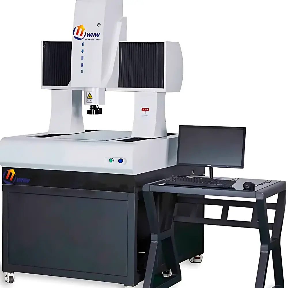
YANRUN YR5040-M Bridge-Type Fully Automatic 3D Vision Measuring Machine
| Brand | YANRUN |
|---|---|
| Origin | Shanghai, China |
| Manufacturer Type | OEM Manufacturer |
| Region of Origin | Domestic (China) |
| Model | YR5040-M |
| Operation Mode | Fully Automatic |
| XY Measurement Accuracy | (2.6 + L/200) µm |
| Z-Axis Measurement Accuracy | (5 + L/200) µm |
| Enclosed Linear Encoder Resolution | 1 µm |
| XY Axis Speed | 280 mm/s |
| Z-Axis Speed | 100 mm/s |
| Optical Magnification | 0.7×–4.5× |
| System Magnification | 21×–200× |
| Camera | Hikvision GigE Color Industrial Digital Camera |
| Surface Illumination | 5-Ring 8-Zone LED Cold Light Source, 256-Step Brightness Control |
| Profile Illumination | LED Cold Light Source, 256-Step Brightness Control |
Overview
The YANRUN YR5040-M is a high-precision bridge-type 3D vision measuring machine engineered for metrological-grade geometric inspection in quality control laboratories, precision manufacturing facilities, and R&D centers. It employs non-contact optical measurement principles based on high-resolution digital imaging, telecentric optics, and calibrated coordinate metrology—compliant with ISO 10360-7 (coordinate measuring machines using optical distance sensors) and aligned with the traceability framework of ISO/IEC 17025. The system integrates a rigid 00-grade granite bridge structure, precision linear motion stages driven by Mitsubishi servo motors, and closed-loop 1 µm resolution optical encoders on all three axes (X/Y/Z), ensuring mechanical stability and thermal drift resistance under controlled environmental conditions (20 °C ±2 °C, <0.002 g vibration at <15 Hz). Designed for repeatable sub-micron-level dimensional verification, it supports both manual operator-guided and fully automated CNC-driven measurement routines across parts up to 500 × 400 mm in footprint and 200 mm in Z-height—capable of handling loads up to 80 kg.
Key Features
- Rigid metrology-grade architecture: 00-grade granite base and column with surface flatness ≤3 µm; Taiwan HIWIN precision linear guideways with preloaded rolling elements.
- High-speed motion control: X/Y axis rapid traverse at 280 mm/s; Z-axis vertical movement at 100 mm/s with DC servo motor and electromagnetic brake for positional hold during measurement.
- Optical subsystem: 6.5:1 zoom telecentric lens with manual magnification adjustment (0.7×–4.5×); no recalibration required after zoom change due to software-based pixel-scale compensation.
- Dual-illumination system: Independent 5-ring 8-zone surface LED illumination and coaxial contour LED backlight—each controllable in 256 brightness steps via software logic for optimal edge contrast across diverse material finishes (matte, reflective, translucent).
- Imaging sensor: Hikvision Gigabit Ethernet color industrial camera with progressive scan CMOS sensor, supporting real-time image streaming and low-noise frame capture at configurable exposure times.
- Temperature compensation algorithm: Dynamically adjusts dimensional output using real-time ambient temperature input and user-defined coefficient of thermal expansion (CTE) for workpiece material—enhancing measurement accuracy per ISO 230-3 Annex D.
Sample Compatibility & Compliance
The YR5040-M accommodates a broad range of manufactured components including machined metal parts, injection-molded plastics, PCBs, stamped sheet metal, precision gears, and medical device housings. Its 500 × 400 mm measurement volume and 200 mm Z-clearance enable full-field inspection of medium-format assemblies without disassembly. The system complies with ISO 9001 quality management requirements and supports GLP/GMP audit readiness through secure user access levels, electronic signature capability, and full measurement data traceability—including timestamped .rst task logs, SPC-ready CSV exports, and revision-controlled report templates (Word, Excel, PDF, DXF). Optional Renishaw MCP 3D tactile probe integration extends functionality to hybrid measurement workflows requiring contact-based feature validation per ISO 14253-1.
Software & Data Management
The proprietary CNC4000 control platform provides deterministic real-time motion coordination and synchronized image acquisition. The embedded CNC Smart Metrology Software delivers comprehensive geometric analysis: point, line, circle, ellipse, spline, slot, radius, and multi-feature composite constructions (e.g., best-fit centerlines, tangents, perpendicular bisectors). Form and position tolerancing adheres to ASME Y14.5 and ISO 1101 standards—supporting GD&T evaluation of straightness, circularity, parallelism, perpendicularity, angularity, concentricity, and position. Advanced image processing includes texture segmentation, multi-region edge extraction, auto-focus height mapping, and panoramic image stitching. CAD interoperability is achieved via native DXF import/export, overlay-based GD&T annotation, and deviation color-mapping against nominal geometry. All reports include full metadata (operator ID, timestamp, calibration certificate ID, environmental log) and support 21 CFR Part 11-compliant electronic records when deployed with validated IT infrastructure.
Applications
This instrument serves critical metrology functions across aerospace component verification (e.g., turbine blade root profiles), automotive powertrain inspection (valve seats, gear tooth geometry), electronics manufacturing (SMT pad alignment, BGA ball coplanarity), and biomedical device QA (catheter hub dimensions, implant surface finish verification). Its automated batch measurement mode enables unattended operation for high-volume production sampling, while its navigable image map and CAD-guided measurement path generation accelerate first-article inspection cycles. The system is routinely deployed in ISO 17025-accredited calibration labs for intermediate verification of gauge blocks, ring gauges, and step masters—particularly where optical comparators or CMMs lack throughput or flexibility.
FAQ
What standards does the YR5040-M comply with for measurement uncertainty reporting?
It follows ISO/IEC 17025 Annex A.4 guidelines for uncertainty estimation in dimensional metrology, incorporating contributions from encoder resolution, thermal expansion, lens distortion, and image noise—documented in its factory calibration certificate.
Can the system perform true 3D surface topography reconstruction?
No—it performs 2.5D height profiling via focus-based Z-scan (focus variation metrology), not full areal 3D scanning; for quantitative surface roughness (Ra, Rz), a dedicated confocal or interferometric profiler is recommended.
Is third-party calibration certification available?
Yes—NIST-traceable calibration services are offered by authorized YANRUN metrology partners, including full ISO 10360-2 volumetric performance verification and certificate of conformance.
Does the software support statistical process control (SPC) charting natively?
Yes—the integrated SPC module imports .rst task files and generates X-bar/R charts, capability indices (Cp/Cpk), and outlier detection alerts compliant with AIAG SPC manual v2.
What is the recommended maintenance interval for optical calibration?
Lens calibration is performed automatically at startup; full system verification (including encoder linearity and stage orthogonality) is advised every 12 months or after 2,000 operational hours, per ISO 10360-2 Clause 7.3.


