YANRUN MC030-YRMCT3000/0.3 Dual-Axis Photoelectric Autocollimator
| Brand | YANRUN |
|---|---|
| Origin | Shanghai, China |
| Manufacturer Type | Manufacturer |
| Model | MC030-YRMCT3000/0.3 |
| Focal Length | 300 mm |
| Aperture | 48 mm |
| Measurement Range | 0–35 m |
| Angular Resolution | 0.0001″ to 1″ (adjustable in arcseconds) |
| Field of View (X/Y) | 1900″ × 1400″ |
| Accuracy (Center) | ±0.3″ (0–±100″), ±0.5″ (0–±600″) |
| Sampling Frequency | ≤30 Hz |
| Interface | USB 2.0 |
| Operating System | Windows 7 or later (64-bit) |
| Dimensions | 388 × 135 × 125 mm |
| Weight | 5.0 kg |
Overview
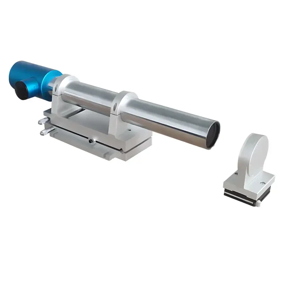
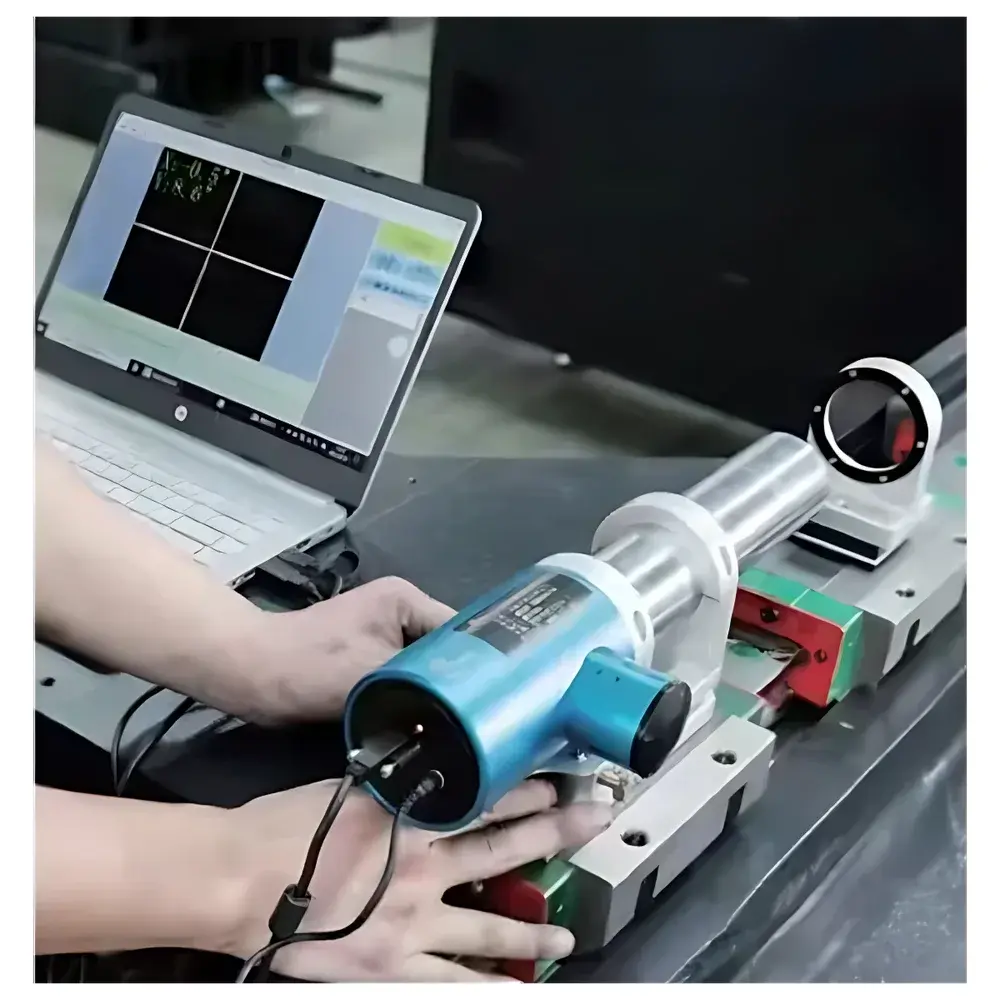
The YANRUN MC030-YRMCT3000/0.3 Dual-Axis Photoelectric Autocollimator is a precision angular metrology instrument engineered for high-reproducibility measurement of minute angular deviations in two orthogonal axes (X and Y) simultaneously. It operates on the fundamental optical principle of autocollimation: a collimated beam—generated by projecting a reticle image through a 300 mm focal-length objective lens—is reflected perpendicularly from a planar mirror and re-imaged onto a high-resolution photodetector array located at the same focal plane. When the mirror rotates by angle α, the returned reticle image shifts by ΔS = 2f·tan(2α) ≈ 4fα (for small angles in radians), enabling sub-arcsecond angular quantification via pixel-level centroid displacement analysis. This non-contact, drift-compensated methodology eliminates parallax and observer-dependent error inherent in traditional visual autocollimators. Designed for integration into metrology workflows requiring traceable, repeatable angular data—such as alignment of optical benches, calibration of rotary stages, or verification of guideway straightness—the instrument delivers certified accuracy of ±0.3″ within ±100″ range under ISO 10110-5 and ISO 21098 compliant environmental conditions.
Key Features
- Dual-axis synchronous measurement with real-time coordinate acquisition and dynamic error calculation
- Integrated electronic eyepiece with high-sensitivity CMOS photodetector, eliminating subjective aiming bias
- Adjustable angular resolution down to 0.0001 arcsecond (0.005 µrad), configurable via software interface
- Stable, long-life semiconductor LED illumination source (rated >50,000 hours MTBF), thermally stabilized for intensity consistency
- Compact monolithic housing (388 × 135 × 125 mm, 5.0 kg) optimized for field deployment and lab bench integration
- USB 2.0 interface with deterministic latency (<15 ms end-to-end), compatible with Windows 7+ (64-bit) systems meeting minimum CPU requirements (Intel Core i3-4th gen or equivalent)
- Multi-language UI support (English, Chinese, Russian, Korean) with standardized export to Excel-compatible CSV and XLSX formats
- Modular architecture supporting optional accessories—including precision kinematic mounts, retroreflector arrays, and motorized tilt stages—for extended geometrical metrology applications
Sample Compatibility & Compliance
The MC030-YRMCT3000/0.3 is compatible with standard optical flat mirrors (λ/10 surface quality, ≥95% reflectivity at 635 nm), corner cubes, and custom retroreflective targets. Its 48 mm aperture and 300 mm focal length enable effective operation across distances from 0.5 m to 35 m, accommodating both short-baseline machine tool verification and large-scale structural alignment tasks. The system complies with ISO 10110-5 (optical component testing), ISO 21098 (autocollimator performance specification), and supports GLP/GMP audit trails when used with validated software configurations. While not inherently FDA 21 CFR Part 11 compliant, its data logging engine records timestamped raw pixel coordinates, calculated angles, and environmental metadata—enabling third-party validation for regulated environments. All units undergo factory calibration against NIM-traceable angle standards; certificate of calibration includes uncertainty budget per GUM (JCGM 100:2008).
Software & Data Management
The included YANRUN AutoAlign Pro software runs natively on Windows platforms and provides real-time visualization of the reflected crosshair image with sub-pixel centroid tracking. It implements iterative least-squares fitting for distortion correction and supports batch processing of time-series angular data. Measurement modes include static alignment, dynamic tracking (≤30 Hz), and multi-point sequential capture. Data output includes absolute angular deviation, differential tilt between positions, and statistical summaries (mean, SD, max/min). Export options conform to ASTM E29-23 formatting guidelines, with metadata headers specifying instrument ID, calibration date, operator, ambient temperature/humidity, and measurement configuration. Software updates are distributed via secure HTTPS portal; version history and change logs are maintained per ISO/IEC 17025 Clause 5.9.2 requirements.
Applications
- Precision alignment of CNC machine tool guideways, spindles, and linear stages
- Verification of straightness, flatness, perpendicularity, and parallelism per ISO 230-1 and ASME B5.54
- Calibration of high-accuracy rotary tables and goniometers in aerospace component manufacturing
- Optical assembly and collimation of laser cavities, interferometer arms, and telescope optics
- Dynamic angular stability assessment of vibration-isolated optical tables and active damping systems
- Teaching and research in undergraduate and graduate optics laboratories (e.g., wavefront sensing fundamentals, Abbe error analysis)
- Field service metrology for semiconductor lithography tool maintenance and alignment
FAQ
What is the recommended warm-up time before high-precision measurements?
A minimum 15-minute power-on stabilization period is required to achieve thermal equilibrium in the optical path and sensor electronics. For metrological-grade certification, the instrument must be acclimatized in a temperature-controlled environment (±0.5°C) for ≥24 hours prior to calibration.
Does the system support external triggering or synchronization with other instruments?
Yes—via TTL-level input on the accessory port, enabling synchronized capture with motion controllers, laser trackers, or environmental sensors.
Can measurement data be integrated into LabVIEW or MATLAB environments?
Native DLL libraries and documented API functions (C/C++ and .NET) are provided for programmatic control and data ingestion; MATLAB Instrument Control Toolbox and LabVIEW Vision Development Module compatibility is verified.
Is the LED light source replaceable by the user?
No—the LED module is hermetically sealed and calibrated as part of the optical train; replacement requires factory recalibration and is performed only by authorized service centers.
What environmental conditions affect measurement repeatability?
Air turbulence (caused by temperature gradients >0.3°C/m), mechanical vibration (ISO 230-2 Class 3 or better recommended), and stray ambient light (especially >600 nm) degrade signal-to-noise ratio; use of enclosed beam paths or baffles is advised in non-laboratory settings.