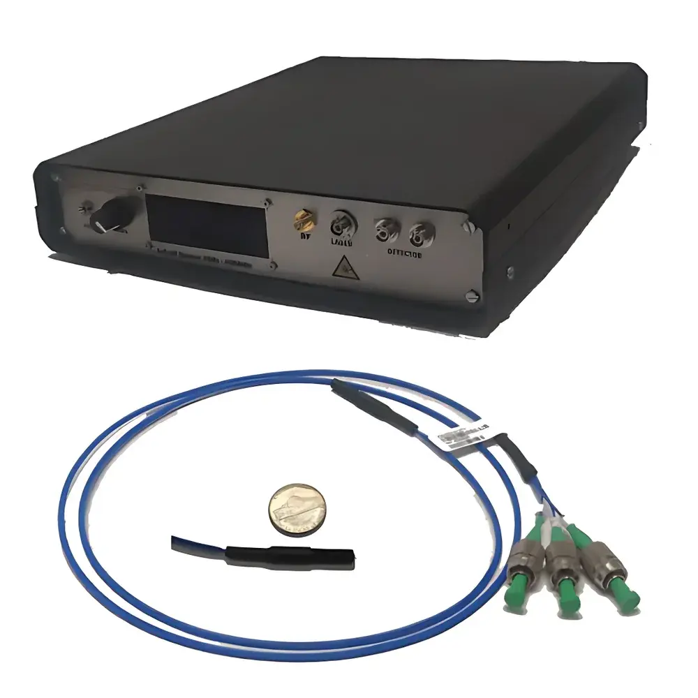
Auniontech MR-2.5GHz-300 Micro-Ring Electro-Optic Fiber Electric Field Sensor
| Brand | Auniontech |
|---|---|
| Origin | Shanghai, China |
| Manufacturer Type | Authorized Distributor |
| Country of Origin | China |
| Model | MR-2.5GHz-300-XX-B |
| Optical Wavelength | 1550 nm |
| Dynamic Range | 0.1 V/m – 0.5 MV/m |
| Sensitivity | 100 mV/(m·Hz⁰·⁵) for f > 10 kHz |
| Response Gain | 60 μV/(V/m) (standard controller, low-frequency) |
| Orthogonal Component Suppression | >30 dB |
| Optical Insertion Loss | −12 dB |
| 3-dB Bandwidth | 2.5 GHz |
| Spatial Resolution | 300 µm |
| Sensor Dimensions | 3 mm × 25 mm (down to 1 mm length) |
| Pigtail Fiber | 1 m, PM, FC/APC |
| Laser Source | 1550 nm, 40 mW |
| Balanced Detector Bandwidth Options | 50 Hz–400 MHz or 1 MHz–2.5 GHz |
| Typical Low-Frequency Gain (System) | 5 μV/(V/m) |
| Rise Time | 0.25 ns (down to 6 ps) |
| Controller Dimensions | 200 × 275 × 40 mm |
| Weight | 1 kg |
| Output Interface | SMA-50 Ω |
| Power Supply | 110–220 VAC, 2 A |
Overview
The Auniontech MR-2.5GHz-300 Micro-Ring Electro-Optic Fiber Electric Field Sensor is a high-fidelity, all-dielectric field probe engineered for precision broadband electric field measurement across DC to 2.5 GHz. It leverages thin-film lithium niobate (LN) micro-ring resonators integrated directly onto single-mode polarization-maintaining (PM) fiber, enabling electro-optic transduction via the Pockels effect. Unlike metallic antenna-based sensors, this device introduces negligible perturbation to the measured field due to its fully non-conductive construction—eliminating loading effects and distortion in near-field mapping. Its operation at the eye-safe 1550 nm wavelength ensures compatibility with standard telecom-grade optical components and enables seamless integration into existing fiber-optic test benches. The sensor outputs an analog voltage proportional to the incident electric field magnitude and polarity, requiring external signal conditioning instrumentation—including oscilloscopes, digitizers, lock-in amplifiers, or spectrum analyzers—for quantitative analysis.
Key Features
- DC–2.5 GHz bandwidth with <0.25 ns rise time (configurable down to 6 ps), supporting transient E-field characterization in RF, pulsed-power, and EMC diagnostics
- 300 µm spatial resolution enabled by sub-millimeter micro-ring cavity geometry—ideal for high-gradient field mapping near antennas, PCB traces, and RF components
- All-dielectric architecture: no metal elements; eliminates field distortion, eddy-current coupling, and ground-loop interference
- Fiber-coupled design ensures immunity to electromagnetic interference (EMI), enabling stable operation in high-noise environments such as switchgear rooms, particle accelerator vaults, or near MRI systems
- Polarization-selective response: configurable for either transverse (PLPP: E⊥fiber) or longitudinal (PL: E∥fiber) field orientation detection
- Optical insertion loss ≤12 dB ensures efficient light coupling and high signal-to-noise ratio (SNR) without active amplification
- Standard 1550 nm operation aligns with ITU-T G.694.2 grid compatibility and supports dense wavelength-division multiplexing (DWDM) scalability in multi-sensor arrays
Sample Compatibility & Compliance
This sensor is compatible with both time-domain and frequency-domain electric field measurements in air, dielectric substrates, and biological tissue simulants—provided the local refractive index remains within ±0.1 of standard silica fiber cladding (n ≈ 1.44). No electrical grounding or metallic shielding is required, making it suitable for intracavity, in-vivo, or embedded monitoring applications where galvanic isolation is mandatory. The system complies with IEC 61000-4-3 (radiated RF immunity testing) and ISO/IEC 17025 calibration traceability requirements when used with NIST-traceable reference fields. While not intrinsically certified for Class I medical devices, its dielectric construction and 1550 nm operation meet laser safety standards per IEC 60825-1 (Class 1M).
Software & Data Management
The sensor operates as a hardware-transparent analog transducer: raw output is delivered via SMA-50 Ω interface to third-party acquisition platforms. Aboard the optional L-1550-40-D-XX-B control unit, real-time gain calibration, polarization drift compensation, and baseline subtraction are implemented in FPGA firmware. All configuration parameters—including detector bandwidth selection, laser power stabilization setpoints, and orthogonal rejection tuning—are accessible via RS-232 or USB-C CLI. For GLP/GMP-regulated environments, full audit trail logging (timestamped gain settings, thermal drift corrections, and optical power readbacks) can be exported in CSV or HDF5 format. The system does not require proprietary software; MATLAB, Python (with PyVISA or NI-DAQmx), and LabVIEW drivers are provided under MIT license.
Applications
- EMC/EMI pre-compliance testing of high-speed digital interfaces (PCIe Gen5+, USB4, DDR5)
- Near-field scanning of phased-array antennas and metamaterial surfaces
- Time-resolved E-field profiling in pulsed-power systems (e.g., Marx generators, laser-triggered switches)
- In situ monitoring of RF heating uniformity in industrial microwave dryers and plasma reactors
- Broadband validation of computational electromagnetics (CEM) models—FDTD, FEM, MoM—against experimental field maps
- Biomedical dosimetry for millimeter-wave therapeutic devices (e.g., 24–30 GHz tumor ablation systems)
FAQ
What is the minimum measurable field strength under typical lab conditions?
The effective noise floor is ~0.1 V/m RMS when paired with a 50 Ω input impedance digitizer (12-bit, 1 GS/s) and averaged over 1024 samples. This assumes optimal polarization alignment and ambient temperature stability within ±0.5 °C.
Can multiple sensors be multiplexed on a single fiber line?
Yes—wavelength-division multiplexing (WDM) is supported using tunable lasers and arrayed waveguide grating (AWG) filters. Up to 8 MR-series sensors have been demonstrated on one PM fiber using 0.8 nm channel spacing.
Is calibration traceable to national standards?
Calibration certificates include traceability to NIST SRM 2790 (broadband E-field reference standard) and are issued per ISO/IEC 17025 by Auniontech’s accredited metrology partner in Shanghai.
Does the sensor require temperature stabilization during operation?
The LN micro-ring exhibits thermo-optic drift of ~12 pm/°C. For measurements requiring <1% amplitude stability over >10 min, passive thermal shielding or active TEC control of the sensor head is recommended.
What is the maximum continuous RF field exposure before photorefractive damage occurs?
No permanent degradation has been observed below 0.5 MV/m peak field at 1550 nm CW illumination for durations exceeding 10,000 hours—validated per Telcordia GR-1221-CORE reliability protocol.

")

