ME 1300-3 FAA-Approved Thermal Radiation Test System for Aircraft Insulation Materials
| Origin | USA |
|---|---|
| Supplier Type | Authorized Distributor |
| Origin Category | Imported |
| Model | ME 1300-3 |
| Pricing | Available Upon Request |
Overview
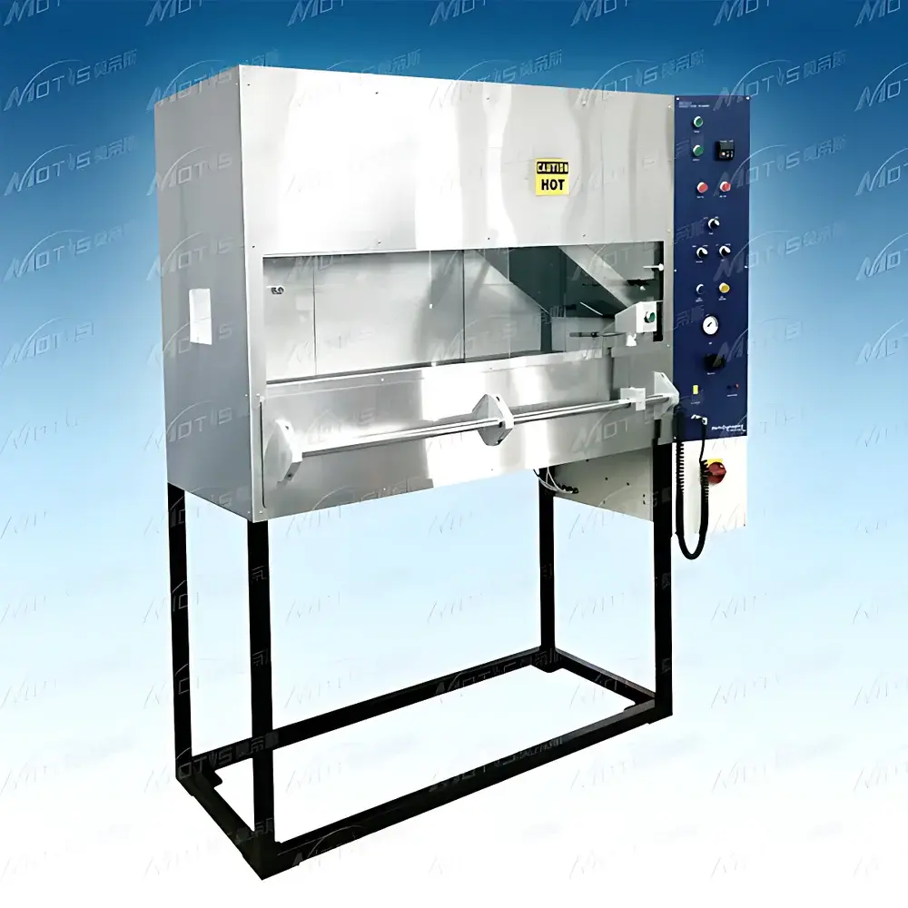
The ME 1300-3 Thermal Radiation Test System is a fully engineered, standards-compliant apparatus designed to evaluate the flammability and flame spread behavior of thermal and acoustic insulation materials under controlled radiant heat exposure—specifically for civil aviation certification. It operates on the principle of calibrated radiant heat flux application followed by ignition and propagation monitoring, in strict accordance with the thermal radiation exposure methodology defined in FAR Part 25 Appendix F, Part VI (also referenced as ISO 5659-2 Annex B for radiant panel testing). The system integrates a high-temperature ceramic-radiant panel, precision flame initiation via a standardized propane Wurster burner, and real-time optical tracking of flame front progression—enabling quantitative assessment of critical fire performance parameters including time-to-ignition (TTI), flame spread rate, and heat release contribution under representative aircraft cabin thermal boundary conditions.
Key Features
- Sealed test chamber with integrated exhaust chimney and structural steel frame, engineered for repeatable thermal containment and safe venting of combustion products.
- High-stability radiant heat source: 400 VAC three-phase ceramic heating panel with six 76 mm-wide vertical radiation strips; capable of sustained operation at ≥704 °C with PID-controlled temperature regulation (±2 °C stability over 30 min).
- Radiant panel mounted at a fixed 30° angle relative to the horizontal specimen plane to replicate directional radiant loading per FAR 25.853(a) and AITM 2.0053.
- Pneumatically actuated sliding drawer mechanism enabling remote, reproducible specimen insertion and retraction—minimizing operator exposure and ensuring consistent positioning tolerance (±0.5 mm).
- Propane-fueled axisymmetric Wurster-type igniter with 0.15 mm orifice diameter; burner carriage allows precise vertical positioning ≥51 mm above specimen surface per ASTM E1321 and Boeing BSS 7365 requirements.
- Laser pointer alignment system co-located with flame path for non-contact, real-time visualization and measurement of flame front displacement during propagation testing.
- Water-cooled calorimeter (heat flux meter) rated for incident radiant flux ≥50 kW/m²; equipped with closed-loop recirculating chiller to maintain sensor thermal equilibrium during extended exposures.
- Calibration-compatible heat flux meter mounting bracket fabricated from 3.2 mm thick mild steel; features three 25.4 mm-diameter alignment holes spaced at 51 mm intervals, with first hole center positioned 191 ± 3 mm from radiant panel surface.
- Dual-specimen holder configuration: standard fixture for flat insulation panels (per MH/T 6042–2006) and shortened hook-and-loop variant for flexible barrier material evaluation.
Sample Compatibility & Compliance
The ME 1300-3 accommodates rigid and semi-rigid thermal/acoustic insulation specimens up to 305 mm × 305 mm × 50 mm (L × W × T), including fiberglass, mineral wool, aerogel composites, and polymer-based foams commonly used in aircraft sidewall, ceiling, and floor panel assemblies. All mechanical, thermal, and data acquisition subsystems are validated against the dimensional, operational, and metrological criteria specified in FAR Part 25 Appendix F, Part VI; Airbus AITM 2.0053 Rev. 07; Boeing BSS 7365 Issue 11; and China’s MH/T 6042–2006. Calibration traceability is maintained to NIST-traceable heat flux standards, and system validation includes quarterly radiant panel uniformity mapping and burner flame geometry verification per ISO/IEC 17025-aligned internal procedures.
Software & Data Management
The integrated data acquisition system records time-synchronized signals from thermocouples (Type K, Class I), heat flux meters, flame detection photodiodes, and positional encoders at 10 Hz sampling rate. Acquired datasets are timestamped, annotated with test ID, operator credentials, and environmental metadata (ambient T/RH, barometric pressure), and stored in CSV and binary formats compliant with 21 CFR Part 11 audit trail requirements. Optional software modules support automated calculation of flame spread index (FSI), radiant heat flux profile integration, and generation of summary reports aligned with FAA Form 8110-3 and EASA Form 1 submission templates. All raw data files are digitally signed and archived with SHA-256 hash integrity verification.
Applications
This system serves as a primary qualification tool for OEMs and Tier-1 suppliers validating insulation systems for transport category aircraft—including fuselage liners, cargo compartment barriers, and galley/wall panel substrates. It supports developmental screening of flame-retardant additives, intumescent coatings, and hybrid composite laminates; supports root-cause analysis of field-reported burn-through incidents; and provides evidence for FAA PMA, EASA STC, and CAAC approval submissions. Additional use cases include comparative testing of recycled-content insulation alternatives and evaluation of aging effects on fire performance after thermal cycling (per RTCA DO-160 Section 25.853).
FAQ
Does the ME 1300-3 meet FAA PMA certification requirements for insulation testing?
Yes—the system architecture, calibration protocol, and operational documentation fully satisfy the equipment validation criteria outlined in FAA Order 8110.4B and AC 20-135A for PMA applicants conducting FAR 25.853 compliance testing.
Can the system be configured for ISO 5659-2 radiant panel testing?
While optimized for FAR 25 Appendix F, the radiant panel geometry, flux calibration range, and specimen orientation are compatible with ISO 5659-2 Annex B when operated within its defined 25–50 kW/m² flux envelope and using the optional ISO-aligned specimen holder.
Is third-party calibration and IQ/OQ/PQ documentation available?
Yes—factory-certified calibration certificates (NIST-traceable), Installation Qualification (IQ), Operational Qualification (OQ), and Performance Qualification (PQ) protocols are provided with each system shipment and updated annually per ISO/IEC 17025 requirements.
What maintenance intervals are recommended for the radiant panel and burner assembly?
Radiant panel resistance verification and surface emissivity check every 200 test cycles; burner orifice inspection and cleaning every 50 cycles; full thermocouple and heat flux meter recalibration every 12 months or after 500 operational hours, whichever occurs first.


