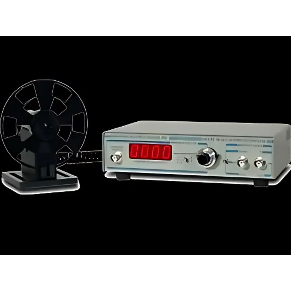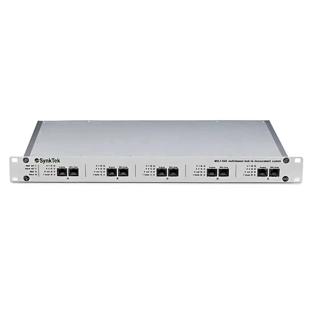
Auniontech MCL1-540 Multi-Channel Digital Lock-in Amplifier with Synchronized Sampling
| Brand | Auniontech |
|---|---|
| Model | MCL1-540 |
| Channels | 10 voltage + 5 current (synchronized) |
| Reference Sources | Internal oscillator or external input |
| Max. Lock-in Frequency Range | DC to 500 kHz |
| ADC Resolution | 18-bit @ 1 MSPS |
| DAC Resolution | 20-bit @ 1.33 MSPS |
| Input Noise Floor | as low as 1.8 nV/√Hz |
| Input Impedance Options | 1 GΩ, 30 GΩ, or 5 TΩ |
| Harmonic Analysis | up to 15 harmonics per channel |
| Phase Resolution | 64-bit |
| Integration Resolution | 96-bit |
| Signal Coupling | DC/AC (cutoff: 0.2 Hz) |
| Output Current Range | 50 mA down to 250 nA |
| Trigger & Phase Marking | TTL-compatible digital I/O via RJ45 |
| Compliance | Supports GLP/GMP-relevant audit trails via software logging |
Overview
The Auniontech MCL1-540 is a high-precision, multi-channel digital lock-in amplifier engineered for synchronized, real-time demodulation of weak periodic signals buried in noise. Based on digital quadrature detection using synchronous sampling ADCs and FPGA-accelerated signal processing, it implements true parallel lock-in measurement across up to 15 analog inputs—10 differential voltage and 5 current channels—without time-division multiplexing. Each channel supports simultaneous dual-phase (X/Y), magnitude (R), and phase (θ) demodulation at user-defined fundamental frequencies and up to 15 independently configurable harmonics. The system operates from DC to 500 kHz, enabling applications ranging from low-frequency transport measurements in quantum materials to high-bandwidth optical interferometry. Its architecture eliminates analog drift and gain mismatch inherent in traditional analog lock-ins, delivering long-term stability and reproducibility required for quantitative physical property characterization.
Key Features
- Fully synchronized 18-bit ADCs (1 MSPS) and 20-bit DACs (1.33 MSPS) across all modules—no sample-and-hold latency or inter-channel timing skew
- Up to five modular signal processing units, each supporting two differential voltage inputs and one current input—with integrated low-noise preamplifiers offering selectable input impedance (1 GΩ, 30 GΩ, or 5 TΩ) and corresponding input bias currents (15 nA, <1 nA, or 10 pA)
- Simultaneous multi-frequency analysis: each input channel hosts three independent lock-in engines, each configurable with unique reference frequency, time constant, filter slope, and harmonic order
- Real-time FFT and oscilloscope visualization of raw and demodulated waveforms—including DC component extraction and spectral decomposition—via native software interface
- Digital I/O integration: dedicated TTL-compatible trigger input/output, phase marker output, and external reference synchronization via RJ45; BNC connectivity supported via optional BB-BNC breakout box
- Auto-ranging input stage with ±10 V full-scale range and sub-nanovolt sensitivity; output stages support ±10 V, ±1 V, ±0.1 V ranges with <10 nV/√Hz output noise (at ±0.1 V range)
Sample Compatibility & Compliance
The MCL1-540 is routinely deployed in cryogenic, ultra-high-vacuum, and electromagnetic-shielded environments for direct impedance spectroscopy, AC susceptibility, differential conductance (dI/dV) mapping, and Hall effect array readout. Its high-input-impedance frontends ensure minimal loading on high-impedance sensors (e.g., pyroelectric detectors, MEMS resonators, or nanoscale tunnel junctions), while the 5 TΩ option enables stable operation with insulating samples and electrochemical interfaces. All firmware and host software comply with data integrity requirements for regulated research: timestamped acquisition logs, immutable parameter snapshots, and exportable metadata conform to ISO/IEC 17025 documentation practices. While not FDA-certified, the system supports 21 CFR Part 11–compliant audit trail generation when used with validated third-party data management platforms.
Software & Data Management
The native control suite provides cross-platform (Windows/Linux/macOS) access to real-time spectrum analysis, parametric sweeps, and closed-loop feedback scripting. Raw and processed data are stored in HDF5 format—self-describing, hierarchical, and compatible with Python (h5py), MATLAB, and LabVIEW. Built-in FFT engine supports windowed spectral estimation (Hanning, Blackman-Harris) with adjustable resolution bandwidth and overlap averaging. For automated experiments, the API exposes full register-level control over demodulator configuration, DAC output sequencing, and trigger routing. Optional real-time feedback module enables PID-controlled modulation depth or frequency tuning based on lock-in output—critical for laser frequency stabilization or adaptive resonance tracking.
Applications
- Quantum transport: multi-terminal resistance mapping, Shubnikov–de Haas oscillations, and Josephson junction characterization
- Materials science: AC calorimetry (3ω method), thermal conductivity imaging, and dielectric spectroscopy
- Optics & photonics: Pound–Drever–Hall laser locking, heterodyne interferometry, and photothermal deflection spectroscopy
- Sensors & instrumentation: strain gauge bridge readout, piezoelectric transducer calibration, and microcantilever resonance tracking
- Correlative measurements: synchronized acquisition across multiple physical probes (e.g., STM bias + AFM deflection + thermal emission)
FAQ
What is the maximum number of independent lock-in measurements possible simultaneously?
Up to 15 fundamental lock-in measurements per channel—plus 15 additional harmonics per channel—can be computed in parallel, resulting in up to 450 simultaneous demodulated outputs (X, Y, R, θ) across the full 15-channel configuration.
Can the MCL1-540 perform true DC-coupled measurements?
Yes. All inputs support true DC coupling with 0.2 Hz high-pass cutoff in AC mode; DC offset is extracted and reported as part of the lock-in output vector, enabling absolute voltage/current quantification alongside AC components.
Is external synchronization supported for multi-instrument experiments?
Yes. The system accepts external TTL or sine-wave reference signals via dedicated BNC or RJ45 ports, and provides programmable phase-locked trigger outputs for coordinating with pulse lasers, cryostat controllers, or scanning probe systems.
How is noise performance verified and traceable?
Input-referred voltage noise is specified per frontend configuration (e.g., 1.8 nV/√Hz @ 1 GΩ) and measured per IEEE Std 1005–2018 guidelines using calibrated thermal noise sources; factory test reports include spectral density plots and Allan deviation curves.
Does the system support third-party automation frameworks?
Yes. A documented C/C++ SDK and Python bindings (PyMCL) enable integration with EPICS, National Instruments VeriStand, and custom LabVIEW or MATLAB instrument drivers.