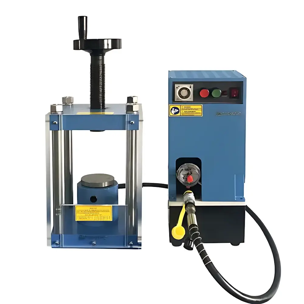
KJ GROUP CIP-22MAF Split-Body Micro Isostatic Press
| Brand | KJ GROUP |
|---|---|
| Origin | Liaoning, China |
| Model | CIP-22MAF |
| Type | Semi-Automatic Isostatic Pellet Press |
| Max Working Force | 11.5 T |
| Max System Pressure | 50 MPa |
| Cylinder Stroke | 15 mm |
| Cylinder Diameter | Φ85 mm |
| Overall Dimensions (Press) | 220 × 240 × 700 mm |
| Control Box Dimensions | 260 × 150 × 500 mm |
| Working Chamber | 140 × 140 × 350 mm |
| Weight | 73 kg |
| Power Supply | AC 220 V, 50/60 Hz, 150 W |
Overview
The KJ GROUP CIP-22MAF Split-Body Micro Isostatic Press is a compact, laboratory-scale cold isostatic pressing (CIP) system engineered for precise densification and shaping of powder-based specimens under uniform hydrostatic pressure. Operating on the principle of Pascal’s law, the unit transmits hydraulic pressure—generated via an oil-driven piston and regulated through a dedicated control cabinet—to a sealed elastomeric mold immersed in a pressurized fluid medium (typically deionized water or low-viscosity oil). This ensures isotropic stress distribution across all surfaces of the sample, minimizing internal shear stresses and enabling high green density with exceptional dimensional uniformity. Designed specifically for academic research laboratories and materials development groups, the CIP-22MAF supports reproducible sample preparation workflows for advanced ceramics, hardmetals, refractory composites, and functional oxide powders—where controlled compaction geometry and minimal density gradients are critical to downstream sintering performance.
Key Features
- Split-body modular architecture: Separates the high-pressure cylinder assembly from the electronic control unit, facilitating safe maintenance, spatial flexibility in lab layout, and simplified transport or reconfiguration.
- Stable pressure retention: Engineered hydraulic circuitry—including precision-machined valve manifolds and low-leakage sealing interfaces—maintains set pressure within ±0.3 MPa over extended dwell periods (up to 30 min), ensuring consistent green body consolidation.
- Direct-force calibration display: Integrated digital pressure gauge displays real-time system pressure in MPa; scale conversion is pre-calibrated so that 1 MPa ≡ 0.23 T (based on Φ85 mm cylinder area), eliminating manual unit conversion during operation.
- Contamination-minimized design: Multi-stage static and dynamic seals (nitrile rubber O-rings + fluorocarbon backup rings) prevent hydraulic oil migration into the pressurization chamber, preserving sample purity and reducing routine cleaning intervals.
- Integrated safety interlocks: Mechanical stop limit at 15 mm stroke, pressure relief valve rated at 55 MPa, and mandatory mold compatibility verification (exclusive use of KJ GROUP–certified CIP-22MAF molds) enforce operational boundaries per ISO 12100:2019 risk assessment guidelines.
Sample Compatibility & Compliance
The CIP-22MAF accommodates cylindrical, rectangular, and custom-shaped elastomeric molds (e.g., silicone or polyurethane) with maximum outer dimensions of 140 × 140 × 350 mm. Compatible powder systems include alumina, zirconia, silicon carbide, tungsten carbide–cobalt blends, ferrites, and lithium-ion cathode precursors. All mold inserts must conform to ASTM B964–22 Annex A1 specifications for isostatic mold integrity testing. The system complies with CE machinery directive 2006/42/EC (as applied to laboratory equipment), IEC 61000-6-3 EMI emission standards, and incorporates grounding provisions aligned with IEC 61000-6-2 immunity requirements. While not certified for GMP manufacturing, its pressure logging capability supports GLP-compliant documentation when paired with external data acquisition hardware.
Software & Data Management
The CIP-22MAF operates via a standalone analog-digital hybrid controller with no embedded firmware or network interface. Pressure ramp rate, dwell time, and final hold pressure are manually selected using calibrated potentiometers and push-button sequencing. For traceability, users may connect a Class 0.1 accuracy external pressure transducer (e.g., Honeywell PX3X series) to a PC-based DAQ system (e.g., National Instruments USB-6009) to record time-stamped pressure profiles. Raw data export in CSV format enables post-processing in MATLAB or Python for statistical process control (SPC) analysis. Audit trails—required under FDA 21 CFR Part 11 for regulated environments—must be implemented externally via validated third-party software solutions.
Applications
- Pre-sintering densification of ceramic green bodies for TEM cross-sectioning and microstructural analysis.
- Consolidation of nanostructured metal oxide powders prior to spark plasma sintering (SPS).
- Manufacture of standardized reference pellets for XRF and XRD quantitative calibration.
- Development of functionally graded materials (FGMs) using layered powder filling techniques under isostatic constraint.
- Process parameter mapping studies correlating green density (measured by Archimedes’ method per ASTM C20–21) with applied isostatic pressure and dwell duration.
FAQ
Can I use molds designed for larger isostatic presses with the CIP-22MAF?
No. Only KJ GROUP–supplied molds certified for the CIP-22MAF platform may be used. Interchange with higher-tonnage systems violates mechanical safety margins and voids liability coverage.
What is the maximum allowable operating pressure for this unit?
The absolute maximum system pressure is 50 MPa. However, the maximum recommended working force is strictly limited to 11.5 T (equivalent to ~40.3 MPa at Φ85 mm cylinder area) to preserve long-term seal integrity and structural fatigue life.
Is the system compatible with corrosive fluids such as ethanol or acetone?
No. Only deionized water or ISO VG 32 mineral oil is approved for use in the pressure chamber. Organic solvents degrade elastomer seals and compromise pressure containment.
Does the control box support remote start/stop via TTL or RS-232?
No. The unit features manual local operation only. External automation requires integration via dry-contact relay outputs (available upon request with optional I/O module).
How often should hydraulic oil be replaced?
Every 12 months or after 500 operating hours—whichever occurs first—using ISO VG 32 anti-wear hydraulic oil meeting DIN 51524 Part 2 specifications. Filter replacement is required at each oil change.


