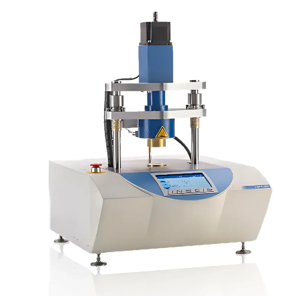
LINSEIS TIM-Tester (TIM L58) Thermal Interface Material Analyzer
| Brand | LINSEIS |
|---|---|
| Origin | Germany |
| Model | TIM-Tester (TIM L58) |
| Measurement Principle | Laser Flash Method (ASTM D5470–17 compliant) |
| Sample Capacity | Single sample per test |
| Test Environment | Ambient temperature operation |
| Accuracy | ±0.1% at 50% stroke, ±0.25% at 100% stroke |
| Thermal Conductivity Range | 0.1–50 W/(m·K) (extendable upon configuration) |
| Sample Forms | Solid, powder, paste, liquid, adhesive, foil |
| Sample Dimensions | Circular Ø20/25/40 mm |
| Thermal Resistance Range | 0.01–8 K/W |
| Temperature Range | −30 °C to 300 °C (configurable) |
| Contact Pressure | 0–16 MPa (dependent on sample area) |
| Cooling System | External water-cooling unit |
Overview
The LINSEIS TIM-Tester (TIM L58) is a precision-engineered thermal interface material (TIM) analyzer designed for quantitative characterization of interfacial thermal transport properties in high-power electronic and electrochemical systems. It operates on the principle of steady-state heat flow measurement under controlled uniaxial compression, fully compliant with ASTM D5470–17 (“Standard Test Method for Thermal Transmission Properties of Thermally Conductive Electrical Insulation Materials”). Unlike transient methods such as laser flash analysis—which measures bulk thermal diffusivity—the TIM-Tester directly quantifies total thermal resistance (Rtotal), contact resistance (Rc), and intrinsic thermal conductivity (k) by resolving the linear relationship between sample thickness (d) and measured thermal resistance (Rtotal = Rc + d/k). This approach enables decoupling of interfacial effects from bulk conduction, a critical requirement for evaluating TIM performance in real-world applications where surface roughness, compliance, and pressure-dependent contact mechanics dominate thermal behavior.
Key Features
- High-precision electromechanical force actuation system with closed-loop displacement control, delivering calibrated contact pressures from 0 to 16 MPa—adjustable based on sample geometry and compliance requirements.
- Integrated dual-zone temperature control: upper heating block (TH) and lower cooling block (TC) independently regulated over −30 °C to 300 °C, enabling isothermal, gradient, and variable-temperature testing protocols.
- Modular sample stage accommodating circular (Ø20/25/40 mm) and square (20×20/25×25/40×40 mm) specimens, with thickness capability spanning 0.01–8 mm (extendable to 20 mm for low-compliance materials).
- Real-time acquisition of thermal resistance, contact resistance, and thermal conductivity using high-stability platinum RTD sensors (Class A tolerance) and low-noise thermopile-based heat flux monitoring.
- Robust mechanical architecture with hardened stainless-steel load train and vibration-damped base, ensuring measurement reproducibility better than ±0.5% across repeated cycles under identical boundary conditions.
Sample Compatibility & Compliance
The TIM-Tester supports heterogeneous material classes essential to modern thermal management: rigid solids (e.g., Vespel™ polyimide, aluminum nitride substrates), compressible elastomers (silicone-based pads), phase-change materials, greases, solder alloys, anisotropic graphite foils, and viscous pastes. Its design conforms to ISO/IEC 17025 requirements for calibration traceability, with force transducers certified to EN ISO 376 and temperature sensors traceable to NIST standards. All test procedures align with ASTM D5470–17 for thermal resistance and conductivity of electrically insulating TIMs, and support supplementary validation against IEC 60584-2 and JEDEC JESD51-14 for junction-to-case thermal characterization in semiconductor packaging. Data integrity meets FDA 21 CFR Part 11 criteria when operated with optional audit-trail-enabled software modules.
Software & Data Management
The proprietary TIM-Control Suite provides intuitive workflow-driven operation—from method definition (pressure ramp rate, dwell time, temperature setpoints) to automated thickness series acquisition and linear regression analysis for k and Rc extraction. Raw sensor data (voltage, temperature, displacement, load) are logged at ≥10 Hz with timestamped metadata (operator ID, sample ID, environmental conditions). Export formats include CSV, Excel, and XML for integration into LIMS or statistical process control platforms. Optional GLP/GMP modules enforce electronic signatures, version-controlled SOPs, and full audit trails—including user actions, parameter changes, and calibration events—ensuring compliance with regulated QA/QC environments.
Applications
- Thermal qualification of TIMs in battery module design: quantifying contact resistance evolution under cycling-induced compression loss and thermal aging at 60–85 °C.
- Interface optimization for power electronics: characterizing thermal impedance of die-attach materials under 1–10 MPa clamping pressure in SiC/GaN inverter modules.
- LED package development: correlating pad thickness variation with junction-to-board resistance in COB and CSP architectures.
- Thermal interface screening for 5G RF front-end modules: evaluating grease reflow behavior and long-term pump-out resistance at 125 °C.
- Material R&D for aerospace-grade composites: measuring through-thickness conductivity and pressure-dependent interfacial resistance of carbon-fiber-reinforced polymer laminates.
FAQ
Does the TIM-Tester comply with ASTM D5470–17?
Yes—the instrument’s mechanical loading architecture, temperature control stability (±0.1 °C), and data acquisition methodology meet all mandatory requirements of ASTM D5470–17 for thermal resistance and conductivity testing of electrically insulating TIMs.
Can it measure liquids or low-viscosity pastes?
Yes—using custom containment fixtures with controlled gap geometry and dynamic pressure compensation to prevent extrusion during compression.
Is external cooling water required for operation?
An external recirculating chiller (15–25 °C supply) is mandatory for TC block stabilization during high-temperature or high-power tests (>100 °C TH or >5 W dissipation).
How is contact resistance separated from bulk conductivity?
By performing sequential measurements across ≥3 discrete thicknesses of the same material batch and applying linear regression to Rtotal vs. d plots—the slope yields 1/k and the y-intercept yields Rc.
What calibration standards are supported?
NIST-traceable reference materials including certified copper (k = 401 W/(m·K)), sapphire (k = 35 W/(m·K)), and compressed graphite foil (k = 150–400 W/(m·K)) are recommended for system verification.


