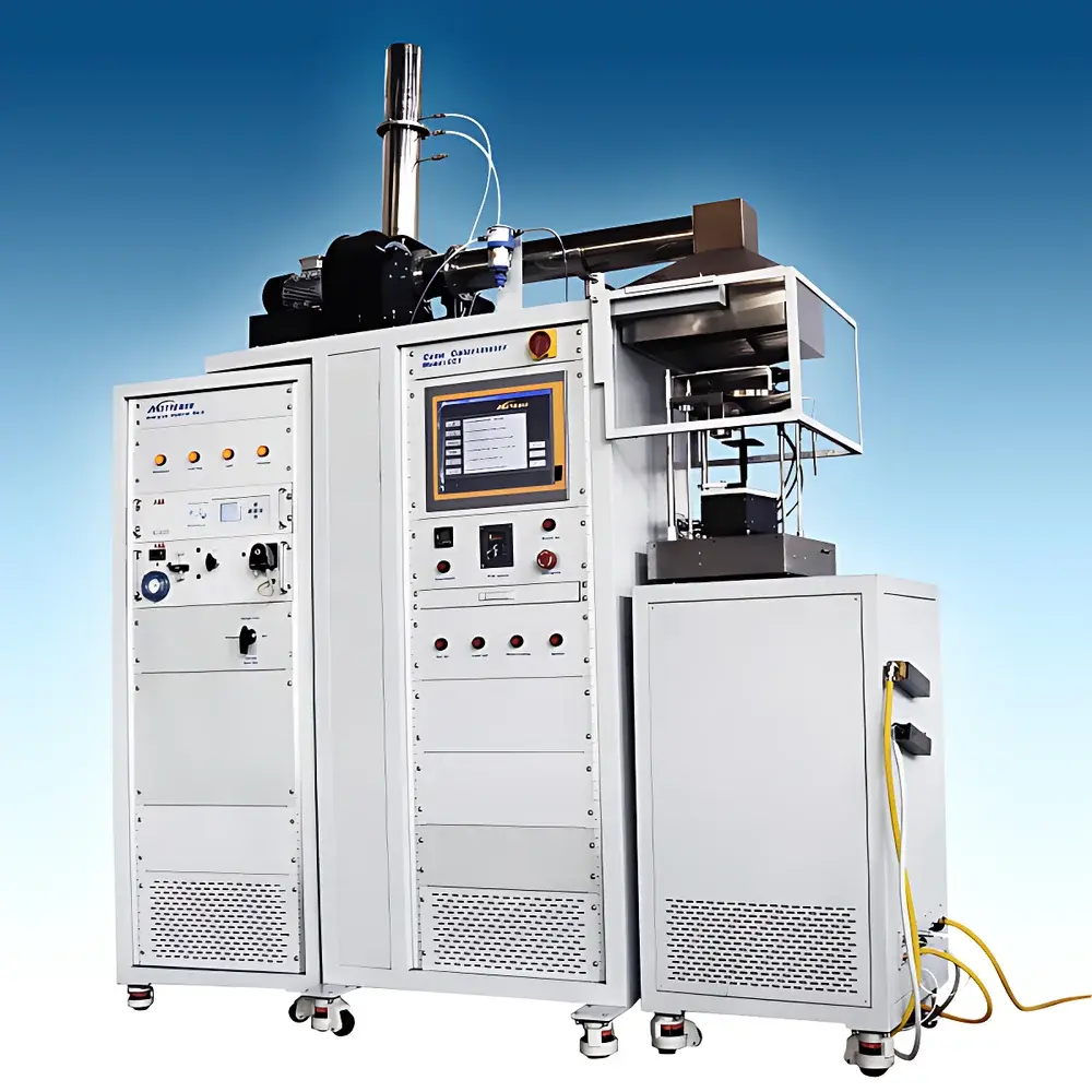
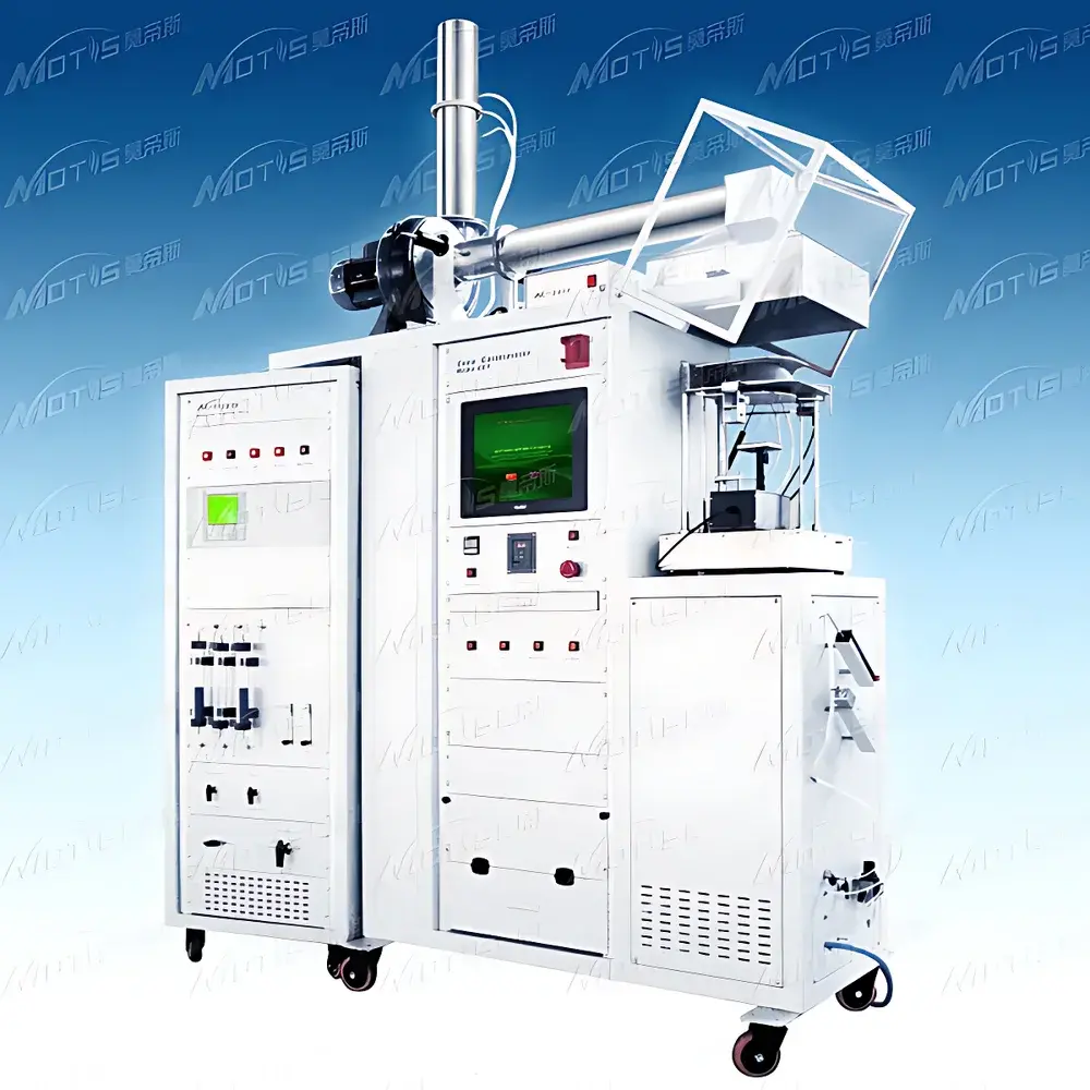
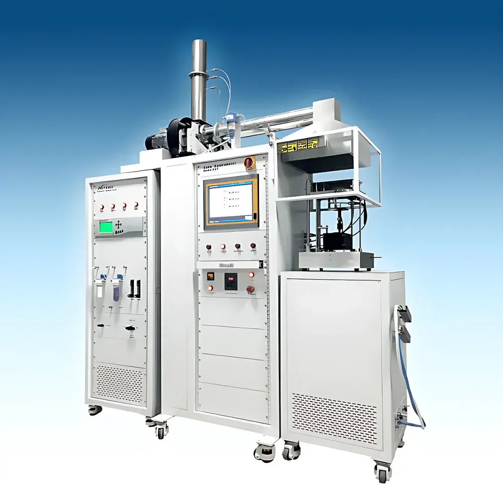
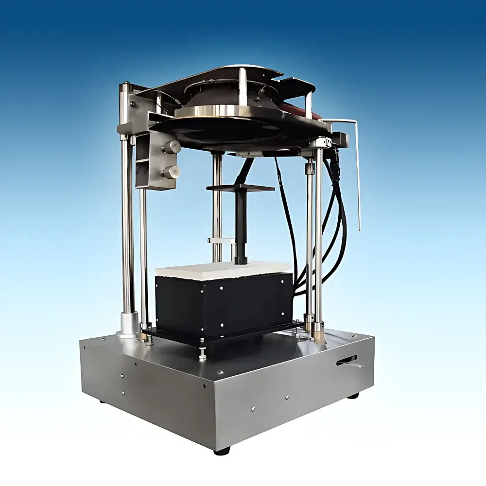
MOTIS CCT Cone Calorimeter
| Brand | MOTIS |
|---|---|
| Origin | Jiangsu, China |
| Model | CCT |
| Heating Source | 5 kW Cone Heater (0–100 kW/m²) |
| Sample Capacity | 100 mm × 100 mm × 50 mm |
| Mass Measurement Range | 0–3000 g (±0.1 g) |
| Oxygen Analyzer | ABB Paramagnetic (0–25% O₂) |
| CO/CO₂ Analyzers | ABB NDIR (CO: 0–1% |
| CO₂ | 0–10%) |
| Smoke Measurement | He-Ne Laser System (632.8 nm) |
| Exhaust Flow Control | 0–50 g/s (±0.1 g/s) |
| Heat Flux Calibration | NIST-Traceable Foil Heat Flux Meter (0–100 kW/m², ±3% accuracy) |
| Compliance | ISO 5660-1 & -2, ASTM E1354, GB/T 16172, BS 476-15 |
Overview
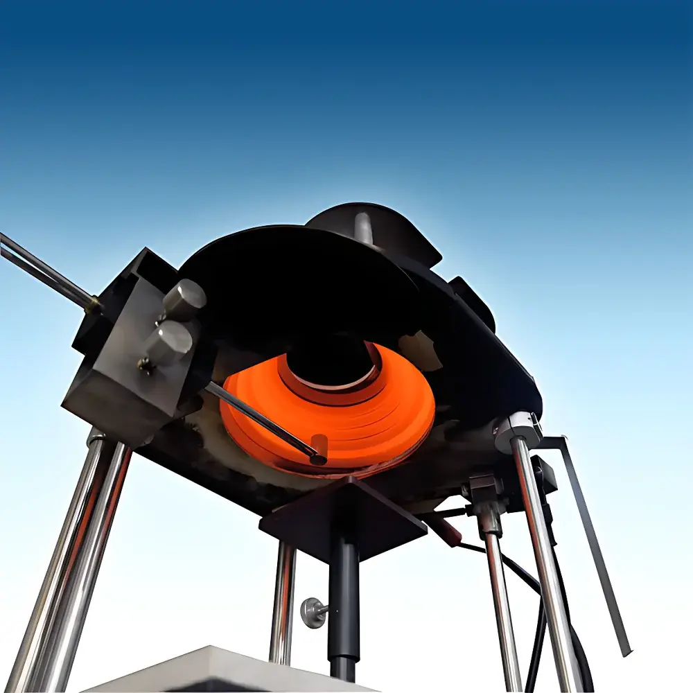
The MOTIS CCT Cone Calorimeter is a precision-engineered bench-scale fire testing instrument designed for quantitative assessment of material combustion behavior under controlled radiant heat exposure. It operates on the oxygen consumption calorimetry principle—first established by NIST researchers in the early 1980s—which correlates the mass of oxygen consumed during combustion with the heat released, based on the empirically validated enthalpy of combustion per unit mass of oxygen (~13.1 MJ/kg O₂, ±5%). This thermodynamic foundation ensures high reproducibility and strong correlation with large-scale fire test data, distinguishing it from qualitative or pass/fail methods such as UL 94 or LOI testing. The system integrates a 5 kW conical heater capable of delivering uniform incident heat flux up to 100 kW/m² across a 50 mm × 50 mm central zone (±2% spatial uniformity), enabling standardized evaluation of heat release rate (HRR), total heat release (THR), effective heat of combustion (EHC), time to ignition (TTI), mass loss rate (MLR), smoke production rate (SPR), and toxic gas yields (CO, CO₂). Its modular architecture supports both standalone operation and integration into larger fire calorimetry platforms.
Key Features
- Modular cabinet design: Separated test chamber and 19-inch analysis rack housing industrial-grade 15″ touchscreen PC for full system control, real-time monitoring, and automated calibration routines.
- High-fidelity sensor suite: ABB paramagnetic O₂ analyzer (0–25% range), dual-channel NDIR CO/CO₂ analyzers (CO: 0–1%, CO₂: 0–10%), laser-based smoke density measurement (He-Ne source, 632.8 nm, dual-detector configuration), and water-cooled NIST-traceable foil heat flux meter (0–100 kW/m², ±3% accuracy, ±0.5% repeatability).
- Precision exhaust management: Adjustable fan-driven ventilation (0–50 g/s, ±0.1 g/s resolution), calibrated sharp-edged orifice plate (57 mm ±1 mm diameter), and annular sampling probe (12-port, positioned 685 mm below hood) ensuring representative gas composition capture.
- Integrated sample handling: Motorized sample stage with 100 mm × 100 mm × 50 mm capacity, high-resolution balance (0–3000 g, ±0.1 g), and auto-positioning 10 kV spark igniter with safety cutoff.
- Comprehensive pre-processing: M&C refrigerated dryer (0–5 °C), KNF diaphragm pump (3 L/min), moisture and CO₂ scrubbers, and automated condensate removal via peristaltic pump—fully compliant with ISO 5660-2 conditioning requirements.
Sample Compatibility & Compliance
The CCT accommodates solid, semi-rigid, and layered specimens—including polymers, composites, foams, textiles, and coated substrates—within defined dimensional and mass limits. Specimens are mounted horizontally on a refractory support tray and exposed to controlled radiant flux without forced flaming, simulating the early growth phase of compartment fires. All operational parameters and data reduction algorithms strictly adhere to internationally harmonized standards: ISO 5660-1 (heat release rate), ISO 5660-2 (smoke and gas analysis), ASTM E1354 (standard test method for heat and visible smoke release rates), BS 476-15 (fire testing of building materials), and GB/T 16172 (Chinese national standard). C-factor calibration—performed using a certified brass burner and traceable propane flow—is validated per ISO 5660-1 Annex B; acceptable C-values fall between 0.035 and 0.045, with ≤5% deviation between consecutive calibrations. The system supports audit-ready documentation for GLP and GMP environments, including full electronic audit trails for sensor calibrations, C-factor logs, and raw data archiving.
Software & Data Management
The embedded control software provides comprehensive instrument management and data acquisition capabilities. It enables multi-point linearization of all analog sensors—including O₂, CO, CO₂, pressure differential, laser extinction, and thermocouple signals—via user-configurable single- or dual-point calibration protocols. C-factor determination is fully automated: users select target thermal input (e.g., 1 kW, 3 kW, or 5 kW), and the software computes instantaneous and averaged C-values per ISO 5660-1, stores historical calibration records, and flags deviations exceeding tolerance thresholds. Gas analyzer time-lag compensation is calculated automatically to synchronize concentration data with mass flow and HRR outputs. A dedicated status dashboard displays real-time health indicators for all subsystems (e.g., O₂ sensor stability, exhaust flow consistency, cooling water temperature). Raw and processed data—including HRR, THR, TTI, MLR, SPR, EHC, CO yield, and smoke optical density—are exported in native Excel format with embedded charts, metadata tagging, and configurable reporting templates compatible with laboratory information management systems (LIMS).
Applications
The MOTIS CCT serves as a foundational tool in fire science research, regulatory compliance testing, and product development across multiple sectors. In polymer R&D, it quantifies flame retardant efficacy by comparing peak HRR reductions, char-forming behavior (via MLR profiles), and smoke toxicity indices (CO/CO₂ ratios, specific extinction area). For construction materials, it informs classification under EN 13501-1 by generating fire performance sub-indices (e.g., FIGRA, MARHE). In transportation—automotive interiors, aircraft cabin materials, and rail composites—it supports certification against FAR 25.853, CS-25.853, and EN 45545-2 through generation of critical fire growth parameters. Academia and national laboratories utilize the system for fundamental studies on pyrolysis kinetics, fire modeling validation (e.g., FDS, CFAST inputs), and development of predictive correlations between small-scale metrics and full-scale fire dynamics. Its compatibility with optional add-ons—including FTIR gas speciation modules and high-speed thermal imaging—enables advanced investigation of gas-phase reaction pathways and surface temperature evolution.
FAQ
What is the oxygen consumption principle, and why is it scientifically robust?
The oxygen consumption calorimetry principle relies on the near-constant enthalpy release per kilogram of oxygen consumed (~13.1 MJ/kg O₂) across most organic materials. This empirical relationship eliminates dependence on flame geometry, soot radiation losses, or incomplete combustion assumptions—making HRR calculation highly accurate and independent of visual flame characteristics.
How frequently must C-factor calibration be performed?
ISO 5660-1 requires C-factor verification before each test series and after any hardware maintenance affecting airflow or gas sampling. Daily calibration checks are recommended for routine QA/QC; documented C-values must remain within 0.035–0.045 and exhibit ≤5% variation between successive determinations.
Does the system comply with FDA 21 CFR Part 11 requirements?
Yes—the software supports role-based user access, electronic signatures, immutable audit trails for all calibration events and test executions, and encrypted data storage—meeting core Part 11 criteria for regulated pharmaceutical and medical device fire safety testing.
Can the CCT operate without external cooling water?
Yes. The integrated portable chiller eliminates dependency on municipal water supply, maintaining stable heat flux meter temperature during extended tests while complying with ISO 5660-1 thermal stability requirements.
What sample preparation standards apply?
Specimens must be conditioned at 23 °C ± 2 °C and 50% ± 5% RH for ≥48 h prior to testing (per ISO 5660-1 Section 6.2). Edge sealing, substrate mounting, and thickness normalization follow material-specific annexes in ASTM E1354 and GB/T 16172.


