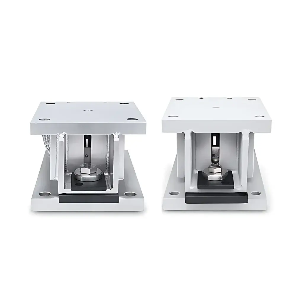
OHAUS i-TMF Series Load Cell Modules
| Brand | OHAUS |
|---|---|
| Origin | Jiangsu, China |
| Manufacturer Type | Manufacturer |
| Country of Origin | China |
| Model | i-TMF |
| Pricing | Upon Request |
| Max Capacity | 10–500 kg |
| Housing Material | Powder-Coated Low-Carbon Steel (i-TMF) / Electropolished 304 Stainless Steel (i-TMFS) |
| Protection Rating | IP68 |
| Operating Environment | –10°C to +40°C, ≤85% RH non-condensing |
| Net Weight | 5.0 kg (10–200 kg models) / 5.9 kg (300–500 kg models) |
| Accuracy Class | C3 (OIML R60) |
| Rated Output | 2.0 ±0.02 mV/V |
| Input Impedance | 460 ±50 Ω |
| Output Impedance | 350 ±3.5 Ω |
| Insulation Resistance | ≥5000 MΩ @ 50 VDC |
| Safe Overload | 150% FS |
| Ultimate Overload | 300% FS |
| Cable Length | 3 m standard |
| optional shielded cables | 15 m / 30 m |
| Sensor Type | LBZ2-CS (carbon steel) / LBZ2-SS (stainless steel), hermetically welded, analog 350 Ω strain gauge |
Overview
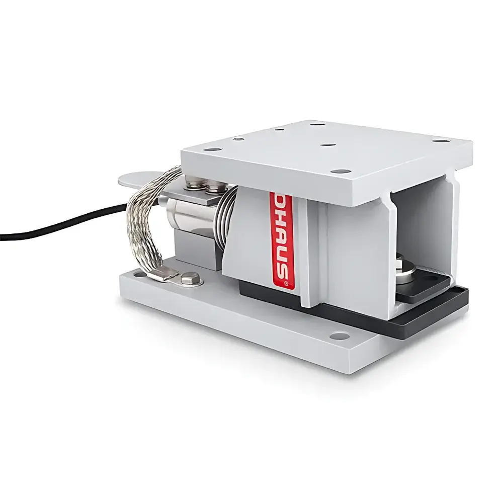
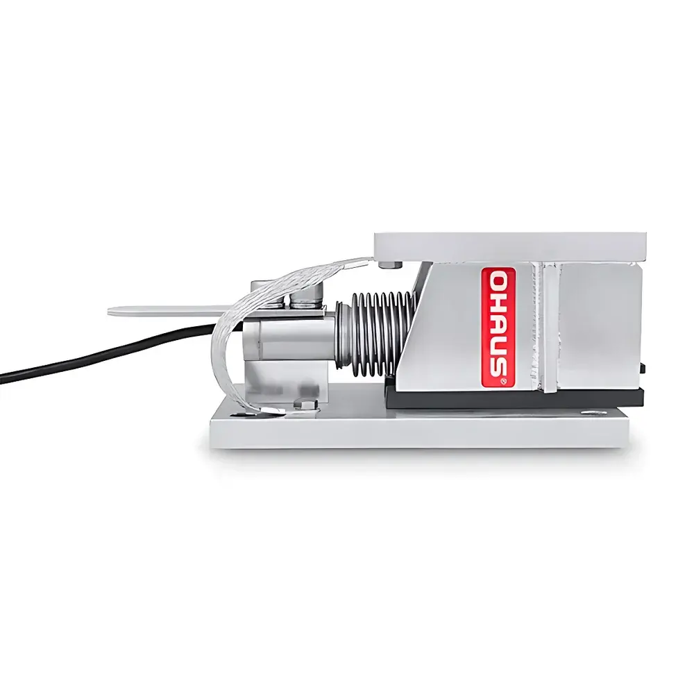
The OHAUS i-TMF Series Load Cell Modules are engineered for high-integrity industrial weighing integration in static and dynamic applications—including tank, hopper, silo, conveyor, and platform scale systems. Built upon precision-welded, hermetically sealed strain gauge technology, each module employs a robust cantilever beam or shear-beam architecture (model-dependent) with integrated mechanical overtravel protection and self-centering pivot geometry. The core transduction principle relies on Wheatstone bridge-based resistance change measurement under applied load, calibrated to OIML R60 Class C3 accuracy standards. Designed for seamless OEM integration, the i-TMF series delivers traceable, repeatable force-to-electrical signal conversion across its full 10 kg to 500 kg capacity range, with temperature-compensated output stability and long-term zero-point retention—critical for continuous process monitoring and batch accountability in regulated environments.
Key Features
- Hermetically sealed, welded-load-cell construction (LBZ2-CS or LBZ2-SS) ensures immunity to moisture, dust, and chemical ingress—validated to IP68 per IEC 60529.
- Self-stabilizing rocker-column mounting system maintains optimal load alignment and minimizes eccentric loading error, enhancing repeatability (< ±0.02% FS typical).
- 360° horizontal constraint design prevents lateral displacement during dynamic operation (e.g., filling, agitation, or vibration), preserving sensor integrity and metrological performance.
- 150% safe overload capacity and 300% ultimate overload tolerance provide operational safety margins without permanent calibration drift.
- Modular mechanical interface supports both sensor-integrated and sensor-agnostic installation configurations—enabling retrofit into legacy frames or new-build integrations.
- Low-maintenance service architecture: sensors are accessible with minimal lifting—no disassembly of support structures required for replacement or recalibration.
Sample Compatibility & Compliance
The i-TMF modules accommodate diverse mechanical interfaces—including flanged, threaded, and pedestal-mount configurations—and are compatible with common industrial load-receiving structures fabricated from carbon steel, stainless steel, or aluminum alloys. All variants comply with OIML R60 Class C3 requirements for industrial weighing instruments and meet EN 45501 (formerly EN 14372) for accuracy, linearity, hysteresis, and temperature effect limits. The electropolished 304 stainless steel i-TMFS models satisfy FDA-compliant surface finish criteria (Ra ≤ 0.8 µm) and are suitable for food, pharmaceutical, and bioprocessing applications where corrosion resistance and cleanability are mandated. IP68-rated housings and shielded cabling (optional 15 m or 30 m lengths) ensure reliable operation in washdown, high-humidity, or outdoor environments.
Software & Data Management
As analog-output devices, i-TMF modules interface directly with industry-standard weighing indicators (e.g., OHAUS AD-4, Mettler Toledo INDxxx, Siemens SIWAREX), PLC analog input cards (±10 V or 4–20 mA), or data acquisition systems supporting mV/V excitation and ratiometric scaling. When paired with compliant indicators featuring audit trail functionality and electronic signature capability, the system supports GLP/GMP-aligned documentation per FDA 21 CFR Part 11. Calibration certificates—including as-found/as-left data, sensitivity, zero balance, and repeatability test records—are generated per ISO/IEC 17025-accredited procedures. Optional stainless steel junction boxes (IP54/IP65/IP67 rated) facilitate centralized signal conditioning and shielding in multi-module installations.
Applications
The i-TMF Series is deployed across sectors requiring certified, durable load measurement: bulk material dosing in chemical manufacturing; ingredient reconciliation in food blending systems; real-time inventory tracking in warehouse pallet scales; reaction mass monitoring in pilot-scale bioreactors; and tension control in web handling machinery. Its dual-material offering (powder-coated carbon steel for cost-sensitive general industrial use; electropolished stainless steel for hygienic or corrosive settings) enables application-specific material selection without compromising metrological performance. The consistent 350 Ω nominal impedance and 2.0 mV/V output simplify analog signal conditioning and reduce channel-to-channel gain mismatch in multi-sensor arrays.
FAQ
What accuracy class do i-TMF modules meet?
All i-TMF and i-TMFS modules conform to OIML R60 Class C3, supporting up to 3,000 verification scale intervals with maximum permissible error (MPE) of ±0.02% of full scale.
Can these modules be used in hazardous areas?
No—the i-TMF series is not intrinsically safe or ATEX-certified. For Zone 1/2 or Div 1/2 environments, consult OHAUS for explosion-proof indicator pairing and barrier-compatible signal conditioning solutions.
Is calibration traceability provided?
Yes—each module ships with a factory calibration certificate traceable to NIST or equivalent national metrology institutes, including sensitivity, zero offset, linearity, and temperature coefficient data.
What is the recommended excitation voltage?
5–12 V DC is optimal; maximum allowable excitation is 18 V DC. Operation outside this range may affect thermal stability and long-term zero point.
Are custom cable lengths available beyond 30 meters?
Shielded twisted-pair cables up to 100 m can be supplied upon request, subject to signal attenuation analysis and compensation via low-noise amplification or digital signal transmission upgrades.