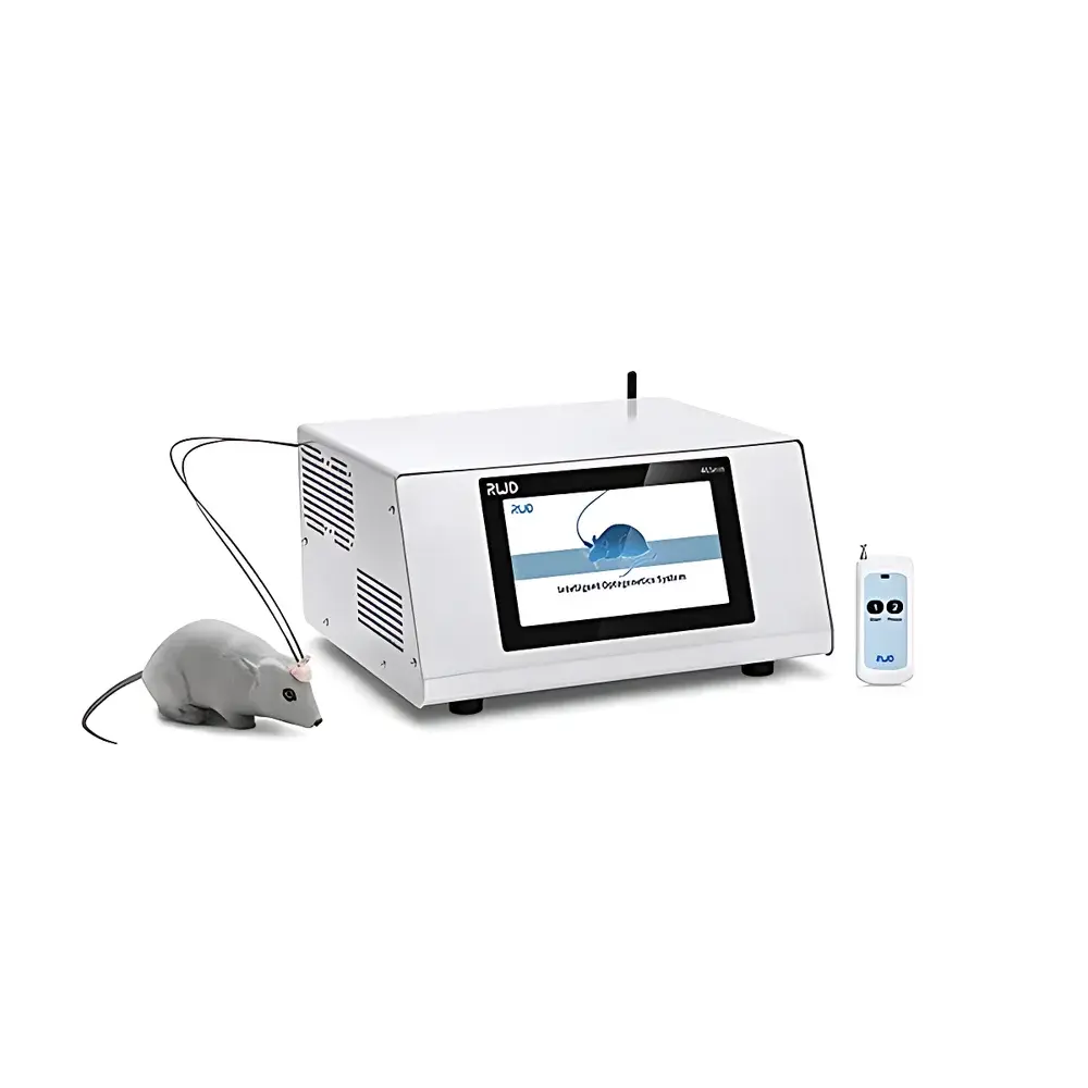
RWD IOS-465/589/635 Integrated Optogenetic Stimulation System
| Brand | RWD |
|---|---|
| Origin | Guangdong, China |
| Manufacturer Type | Manufacturer |
| Product Origin | Domestic |
| Model | IOS-465/589/635 |
| Wavelength Options | 465 nm / 589 nm / 635 nm (selectable) |
| Output Power Range | 0–100 mW (1 mW resolution) |
| Power Stability | ≤ ±1% (RMS deviation < 1% over extended operation) |
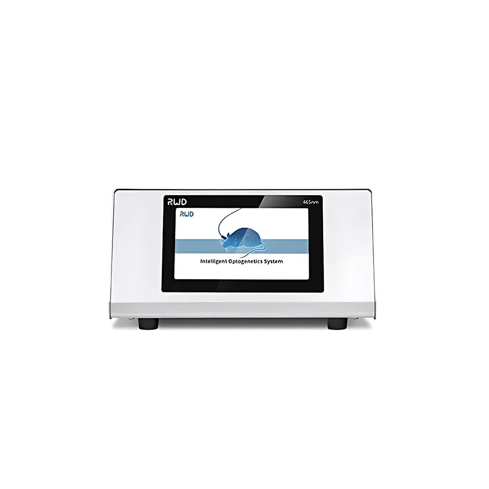
| Touchscreen | 7-inch capacitive display (1024 × 600 px) |
| TTL Output | 10 mV–5 V (trigger), 2–10 V (analog control) |
| Trigger Modes | Edge-triggered, Real-time synchronized, Gate-controlled |
| Remote Control Range | Up to 10 m |
| EMI Compliance | Non-interfering with electrophysiology recordings |
| Calibration | Built-in optical power calibration routine |
| Interface Language | Switchable between English and Chinese |
Overview
The RWD IOS-465/589/635 Integrated Optogenetic Stimulation System is an engineered platform designed for precise, reproducible, and experimentally flexible optogenetic neuromodulation in vivo and in vitro. Leveraging solid-state laser diodes at three biologically validated wavelengths—465 nm (ChR2 activation), 589 nm (ChrimsonR/ReaChR activation), and 635 nm (C1V1/ChRmine excitation)—the system delivers stable, calibrated light output directly coupled to standard multimode optical fibers (e.g., 200 µm or 400 µm core). Its architecture follows the principles of closed-loop photostimulation: real-time power monitoring, temperature-compensated drive current regulation, and low-noise analog/digital signal routing ensure minimal thermal drift and negligible electromagnetic interference with concurrent electrophysiological acquisition (e.g., patch-clamp, extracellular arrays, or whole-cell recordings). The system operates without requiring external power meters or third-party controllers—optical calibration, waveform definition, and hardware synchronization are fully integrated into the embedded firmware.
Key Features
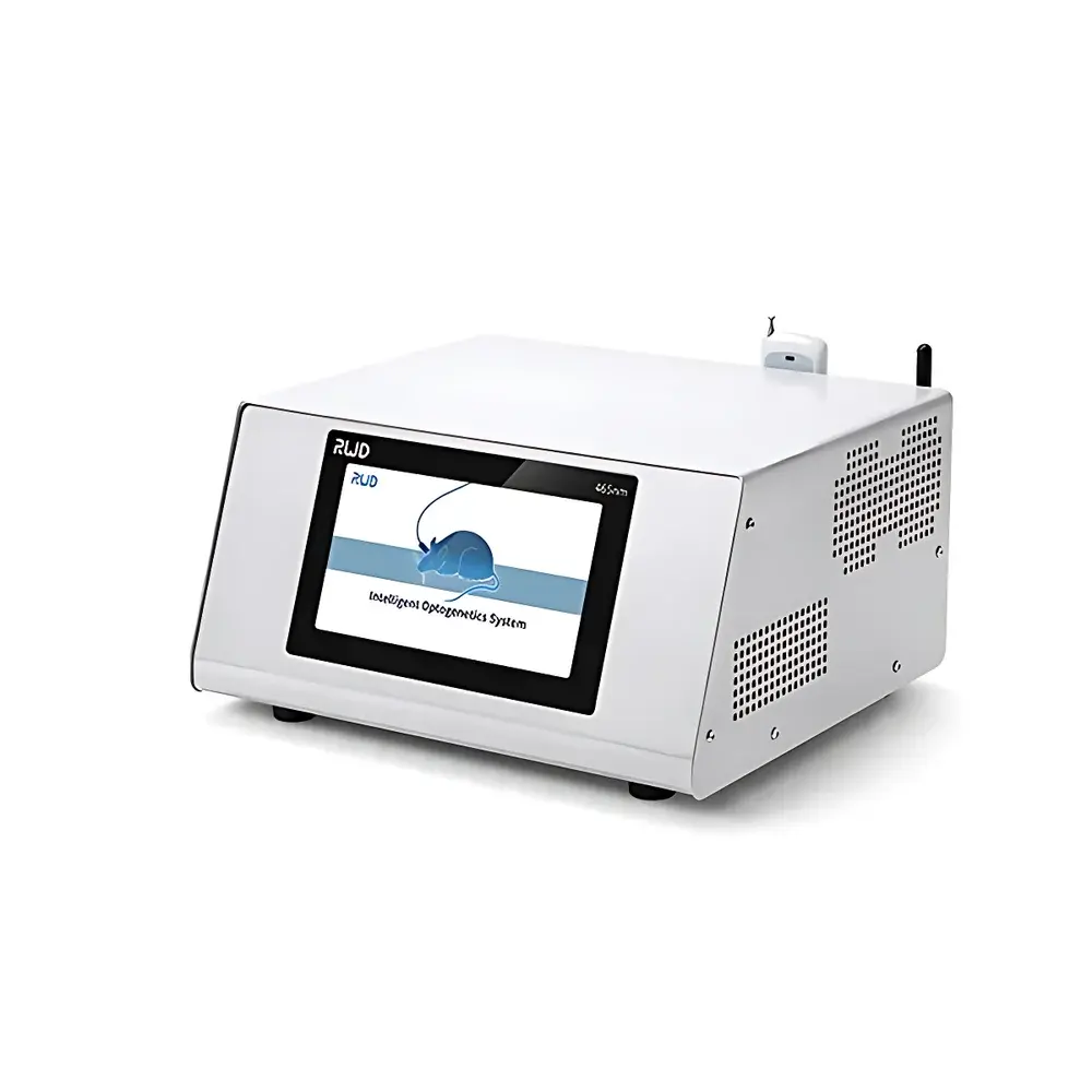
- Monolithic integration of laser source, driver electronics, thermal management, and touchscreen HMI—eliminating inter-unit cabling and alignment uncertainty.
- On-device optical power verification: one-touch “Power Test” mode measures instantaneous output via internal photodiode sensor and auto-writes the validated value into the active stimulation protocol.
- Three hardware-level trigger interfaces: Edge-triggered (TTL rising/falling edge), Real-Time (microsecond-accurate timestamp-synchronized pulse trains), and Gate-mode (light emission enabled only while gate signal remains high)—enabling compatibility with arbitrary waveform generators, DAQ systems (e.g., National Instruments), and behavioral timing controllers.
- EMI-hardened design verified against ISO 13485-aligned test protocols; no observable artifact introduced into 1 kHz–10 kHz band-limited neural recordings.
- Programmable stimulation sequences with up to 16 independent steps per protocol; supports nested loops, variable inter-pulse intervals (1 ms–60 s), and dynamic power ramping (linear or exponential).
- Embedded alarm system with audible buzzer and visual LED indicator activates upon laser diode temperature excursion (>45 °C), end-of-sequence completion, or calibration timeout.
- Full parameter persistence across power cycles; all user-defined protocols, calibration offsets, and language preferences retained in non-volatile memory.
Sample Compatibility & Compliance
The IOS-465/589/635 is compatible with standard 1.25 mm or 2.5 mm ferrule-based fiber optic patch cables (FC/PC, FC/APC, or SMA905 connectors) and integrates seamlessly with commercial electrophysiology rigs (e.g., Intan Technologies, Tucker-Davis Technologies, OpenEphys), calcium imaging setups (e.g., Doric Lenses, Inscopix), and automated behavioral arenas (e.g., ANY-maze, EthoVision XT). It meets CE marking requirements under Directive 2014/30/EU (EMC) and 2014/35/EU (LVD), and conforms to IEC 60825-1:2014 Class 3B laser safety standards. All firmware logs—including power calibration timestamps, trigger event counts, and thermal history—are timestamped and exportable for GLP-compliant experimental documentation.
Software & Data Management
No host PC software installation is required for basic operation—the 7-inch capacitive touchscreen provides full local control with waveform preview, real-time power readout, and editable protocol trees. For advanced workflow integration, the system exposes a documented ASCII-based serial command set (RS-232/USB-C virtual COM port) supporting remote scripting in Python, MATLAB, or LabVIEW. All stimulation logs (start time, duration, wavelength, peak power, trigger source) are stored internally and exportable as CSV via USB flash drive. Audit trails include user login events, calibration actions, and firmware update records—supporting FDA 21 CFR Part 11 compliance when deployed within validated laboratory information management systems (LIMS).
Applications
- In vivo circuit mapping: temporally precise photoactivation/inhibition during awake-behaving rodent experiments, synchronized with video tracking and LFP/MEA acquisition.
- In vitro slice physiology: cell-type-specific depolarization or hyperpolarization in brain slices expressing opsins, with sub-millisecond jitter relative to patch-clamp command pulses.
- Long-term chronic stimulation: stable 72+ hour continuous operation at 30 mW (465 nm) with passive heatsink; validated for longitudinal plasticity studies.
- Multi-wavelength multiplexing: sequential or interleaved delivery of 465 nm and 589 nm light to co-expressing neuronal populations (e.g., ChR2 + ChrimsonR), enabling orthogonal control without spectral crosstalk.
- Behavioral pharmacology: closed-loop light delivery triggered by real-time motion detection or lick-port entry, integrated with drug infusion pumps for causal neuropharmacological interrogation.
FAQ
Does the IOS system require external optical power calibration before each experiment?
No—built-in photodiode feedback and factory-traceable calibration allow on-demand power validation and automatic protocol update without external metering equipment.
Can the system synchronize with third-party DAQ devices using analog voltage signals?
Yes—programmable analog output (2–10 V) mirrors stimulation onset/offset timing and can serve as a hardware sync signal for oscilloscopes, digitizers, or behavior controllers.
Is fiber coupling efficiency affected by wavelength selection?
Coupling loss varies by fiber NA and core diameter; RWD provides wavelength-specific coupling efficiency curves (465 nm: ~82%, 589 nm: ~79%, 635 nm: ~76%) for 200 µm/0.22 NA fiber, measured at 50 mW output.
How is electromagnetic isolation achieved between the laser driver and recording electronics?
Through galvanic isolation of digital control lines, shielded internal PCB layout, ferrite-filtered power rails, and differential TTL signaling—all validated via conducted emission testing per CISPR 11 Group 1 Class B limits.
Are custom fiber connector types or ceramic ferrule geometries supported?
Yes—RWD offers OEM-grade customization including SMA905, FC/PC, FC/APC, and specialized tapered or lensed fiber assemblies, subject to minimum order quantities and mechanical interface specifications.