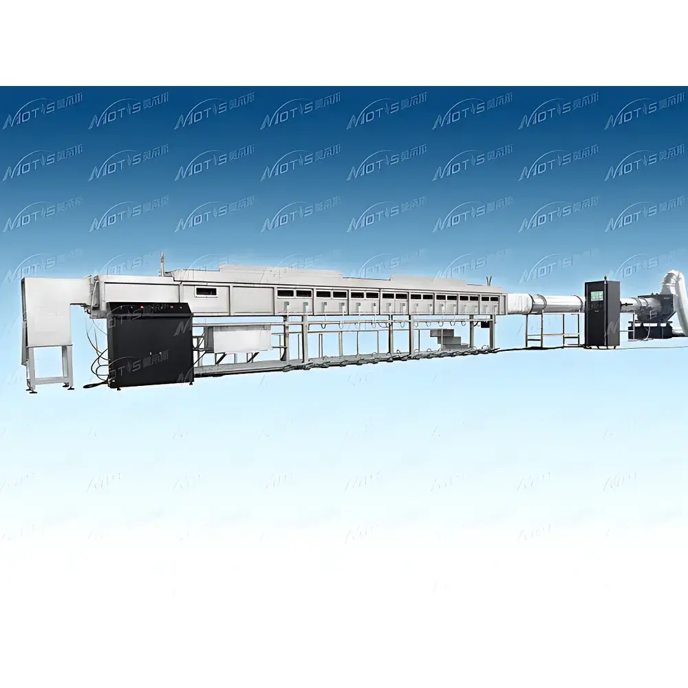
Steiner Tunnel Furnace STF by MOTIS
| Brand | MOTIS |
|---|---|
| Model | STF |
| Standard Compliance | UL 910 / NFPA 262 |
| Chamber Construction | Stainless Steel (304) with Refractory Brick Lining |
| Observation Window | Dual-Layer Quartz Glass |
| Flame Propagation Monitoring | LED Indicator Strip System |
| Smoke Seal | 2 mm 304 Stainless Steel Water-Tight Trough |
| Exhaust Fan | 3 kW, 380 V / 50 Hz, Variable-Frequency Drive, ≥8000 m³/h Capacity |
| Burner | Dual-Orifice Copper Burner, Heat Output Adjustable from 5.3 MJ/min (UL 910 baseline) up to 100 MJ/min via Mass Flow Control |
| Ignition System | High-Voltage Spark Igniter (44 kV / 50 mA, Minimum Electrode Voltage 1.8 kVp) |
| Pressure Monitoring | Differential Pressure Sensor, Range 0–250 Pa, Accuracy ±0.5 Pa (System Accuracy ±2 Pa) |
| Temperature & Smoke Signal Acquisition | 1 Hz Sampling Rate, Linearized Photometric Smoke Density Detection |
| Gas Control | 316 Stainless Steel Mass Flow Controller, Propane Range 0–2.3 g/s, Accuracy ±1% FS (0.6–2.3 g/s), Repeatability ±0.5% FS, NIST-Traceable Calibration |
| Software | Integrated Test Management Platform with Real-Time Logging of Airflow Velocity, Chamber Temperature, Optical Density, and Fuel Consumption |
| Auxiliary Systems | Municipal Water Supply Interface, Methane Gas Delivery Subsystem, Overhead Hoist for Sample Handling |
| Sample Mounting | Stepped Access Platform with Integrated Support for Calcium Silicate Cover Boards |
| Thermal Insulation | High-Temperature Ceramic Fiber Blanket within 304 Stainless Enclosure |
| Application Domain | Horizontal Cable Tray Fire Propagation Testing per UL 910/NFPA 262 for Plenum-Rated Communications Cables |
Overview
The MOTIS Steiner Tunnel Furnace STF is a fully compliant, laboratory-grade fire propagation test system engineered for rigorous evaluation of plenum-rated communication cables under UL 910 and NFPA 262 standards. It implements the standardized horizontal tunnel configuration in which cable samples are mounted horizontally across a 25-ft (7.62 m) long refractory-lined combustion chamber, exposed to a controlled, high-intensity flame at one end while airflow and smoke development are quantified along the length of the tunnel. The furnace replicates real-world conditions found in air-handling spaces—such as raised floors and suspended ceilings—where non-metallic cable trays operate without metallic conduit protection. Its design adheres strictly to the geometric, thermal, and dynamic specifications mandated by UL 910 Annex A and NFPA 262 Clause 6, including prescribed burner geometry, air velocity profiles (typically 2.5 ± 0.2 m/s), and optical density measurement protocols based on Beer-Lambert law-compliant photometric attenuation.
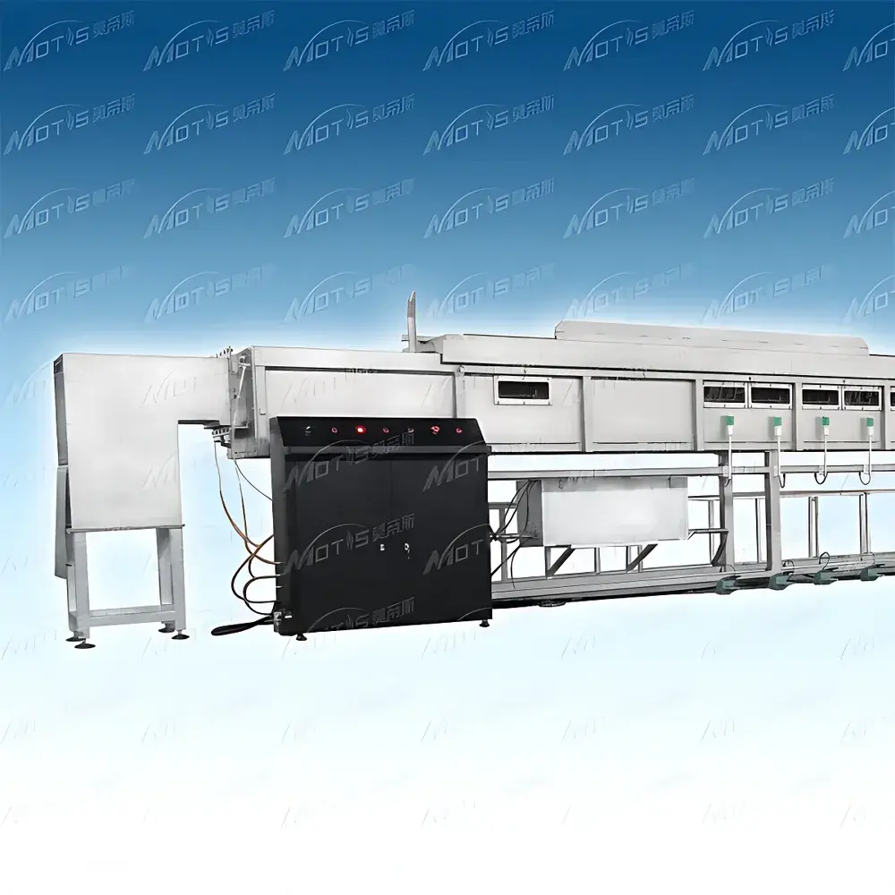
Key Features
- Refractory brick-lined stainless steel (304) combustion chamber engineered to withstand sustained exposure to >800 °C flame impingement while maintaining structural integrity and thermal stability.
- Dual-layer quartz observation windows with integrated LED indicator strip system enabling direct visual tracking and documentation of flame front progression up to 1.5 m beyond the burner zone.
- Water-sealed trough (2 mm 304 SS) ensuring zero leakage of toxic or corrosive combustion effluents during test cycles—critical for operator safety and environmental compliance.
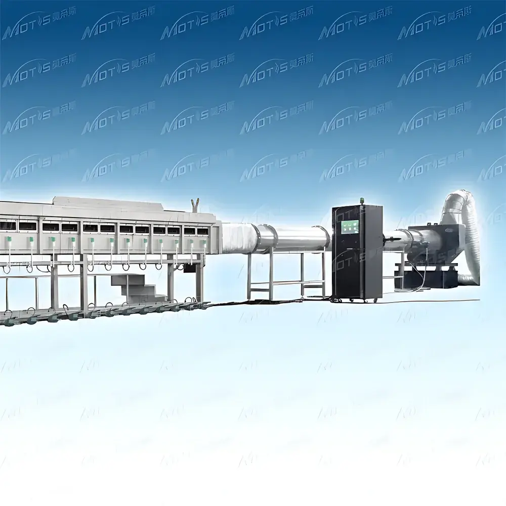
- High-capacity exhaust system (≥8000 m³/h) with variable-frequency-driven centrifugal fan, dynamically regulated to maintain precise airflow velocity and pressure differential across the tunnel per UL 910 Section 7.3.
- Dual-orifice copper burner assembly delivering calibrated heat flux up to 5.3 MJ/min (5000 BTU/min), with extended capacity up to 100 MJ/min via NIST-traceable mass flow control of propane or methane fuel streams.
- Automated high-voltage ignition system (44 kV, 50 mA) with fail-safe electrode monitoring and redundant arc detection, eliminating manual pilot lighting and reducing human error.
- Real-time differential pressure monitoring (0–250 Pa range, ±0.5 Pa sensor accuracy) integrated into the exhaust duct to validate laminar flow conditions and detect deviations affecting smoke layer development.
- Photometric smoke density subsystem featuring linearized signal conditioning, 1 Hz data acquisition, and traceable calibration against reference attenuators per ASTM E622 and ISO 5659-2.
Sample Compatibility & Compliance
The STF accommodates standard UL 910/NFPA 262 cable specimens: single or bundled configurations up to 25 ft in length, mounted on calcium silicate backing boards supported by a water-cooled stainless steel cradle. The stepped access platform enables safe, ergonomic installation and removal of samples—including multi-layer bundles—and facilitates routine inspection of burner alignment, thermocouple placement, and optical path cleanliness. All mechanical, thermal, and gas delivery subsystems are validated per UL’s Equipment Verification Protocol (EVP) and undergo annual third-party verification to support GLP-compliant testing environments. The system meets requirements for FDA 21 CFR Part 11-ready audit trails when paired with optional electronic signature modules, and its pressure, temperature, and optical density outputs are traceable to NIST standards through documented calibration certificates.
Software & Data Management
The embedded STF Control Suite provides synchronized acquisition of airflow velocity, chamber thermocouple readings (Type K, Class I), photometric smoke density (OD units), fuel mass flow rate, and exhaust pressure differentials—all timestamped at 1 Hz resolution. Raw data streams are stored in IEEE-compliant binary format with metadata tagging (test ID, operator, calibration status, ambient conditions). Export options include CSV, XML, and PDF reports pre-formatted to UL 910 Appendix B reporting templates. Audit logs record all parameter modifications, user logins, calibration events, and emergency shutdowns. Optional integration with LIMS platforms is supported via OPC UA and RESTful API endpoints, enabling automated data ingestion into enterprise quality management systems compliant with ISO/IEC 17025 and IEC 61508 functional safety frameworks.
Applications
- Qualification testing of fluoropolymer-jacketed plenum cables (e.g., FEP, PFA, ETFE) intended for installation in air-handling spaces under NEC Article 800 and CSA TIA-568-D.
- R&D validation of novel flame-retardant polymer formulations targeting UL 910 pass criteria: flame spread ≤1.5 m, peak optical density ≤0.5, and average optical density ≤0.15 over 4 min.
- Comparative assessment of jacket material performance under forced-draft fire conditions, including charring behavior, melt drip suppression, and halogen-free smoke toxicity indices.
- Third-party certification testing for UL Listing, CSA Certification, and European CPR classification (EN 50575) when configured with supplementary gas analysis modules (CO/CO₂/HCl).
- Root cause analysis of field cable failures involving smoldering ignition and horizontal flame migration in HVAC plenums.
FAQ
What is the minimum sample length required for UL 910 testing?
Per UL 910 Section 5.2, the test specimen must be 25 ft (7.62 m) in length, installed horizontally across the full tunnel span.
Can the STF be used for NFPA 262 testing with methane instead of propane?
Yes—the dual-fuel capability supports both propane and methane; methane operation requires recalibration of the mass flow controller and adjustment of burner orifice sizing per NFPA 262 Annex C.
Is the water seal trough compatible with continuous operation during multi-cycle testing?
Yes—the trough is actively cooled via municipal water circulation and designed for uninterrupted use across ≥20 consecutive test cycles without maintenance.
Does the system include provisions for particulate or toxic gas emission analysis?
The base configuration includes optical density only; optional add-ons include FTIR-based gas analyzers (CO, CO₂, HCN, HCl) and gravimetric soot collection filters per ISO 5659-2 Annex D.
How frequently must the photometric sensor be recalibrated?
Annual calibration is recommended; however, daily zero-checks using clean-air reference and quarterly linearity verification with neutral density filters are required under GLP protocols.


