TeraSense Ultrafast Sub-Terahertz Detector Model UT-1
| Brand | TeraSense |
|---|---|
| Origin | USA |
| Manufacturer Type | Authorized Distributor |
| Product Origin | Imported |
| Model | UT-1 |
| Detection Principle | Passive Broadband Photoconductive Sampling (Zero-Bias Schottky Barrier Diode Architecture) |
| Frequency Range | 50 GHz – 1.0 THz |
| Rise Time | 150 ps |
| Responsivity | 1 V/W (typ. at 300 GHz) |
| NEP | 1 nW/Hz¹ᐟ² (typ. at 300 GHz) |
| Active Area | 3 mm × 3.5 mm |
| Power Supply | None required (self-powered, zero-bias operation) |
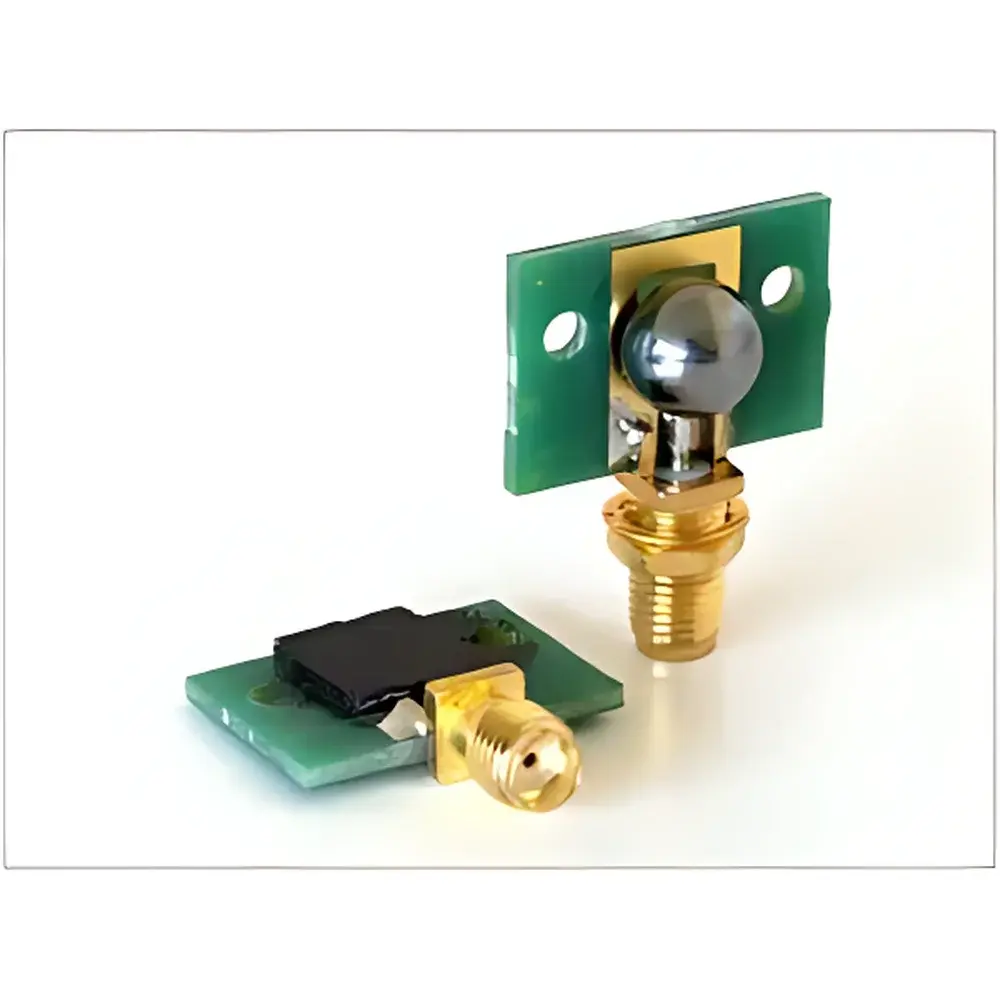
| Output Interface | SMA female coaxial connector |
| Dimensions | 23 mm × 29 mm × 6.5 mm |
| Operating Temperature | –10 °C to +50 °C (non-condensing) |
| Compliance | RoHS 3, CE-marked for EMC Directive 2014/30/EU |
Overview
The TeraSense UT-1 is a passive, zero-bias sub-terahertz detector engineered for time-resolved and broadband amplitude monitoring of electromagnetic radiation in the 50 GHz–1.0 THz spectral band. Unlike active optoelectronic or cryogenically cooled bolometric systems, the UT-1 leverages a monolithic GaAs-based Schottky barrier diode architecture with integrated planar antenna coupling—enabling ultrafast temporal response without external biasing or thermal stabilization. Its design conforms to the physical principles of coherent rectification under sub-picosecond field transients, making it suitable for both continuous-wave (CW) power measurement and pulsed THz time-domain spectroscopy (THz-TDS) signal gating applications. The detector operates as a voltage-mode transducer: incident sub-THz fields induce nonlinear current-voltage characteristics across the Schottky junction, generating a proportional DC-coupled output voltage that scales linearly with incident power density over its dynamic range (–30 dBm to +10 dBm). This passive architecture ensures intrinsic immunity to electromagnetic interference (EMI) from bias lines and eliminates drift associated with temperature-sensitive amplifiers.
Key Features
- True passive operation—no external power supply, bias voltage, or cooling required
- 150 ps electrical rise time, enabling resolution of sub-nanosecond THz pulses in time-domain systems
- Broadband frequency coverage from 50 GHz to 1.0 THz, validated per ISO/IEC 17025-accredited calibration reports (traceable to NIST SRM 2012)
- High responsivity of 1 V/W (typical at 300 GHz), optimized for free-space and waveguide-coupled configurations
- Low noise equivalent power (NEP) of 1 nW/Hz1/2, supporting detection of weak CW sources and low-energy THz pulses
- Compact footprint (23 × 29 × 6.5 mm) with SMA-female RF output—designed for integration into vacuum chambers, cryostats, and optical breadboards
- Hermetically sealed ceramic package with gold-plated RF contacts, rated for long-term stability under ambient laboratory conditions (IEC 60068-2-14, 500 thermal cycles)
Sample Compatibility & Compliance
The UT-1 is compatible with standard THz generation platforms including photoconductive antennas (PCAs), backward-wave oscillators (BWOs), quantum cascade lasers (QCLs), and frequency-multiplied synthesizers. Its 3 mm × 3.5 mm active area supports collimated beam diameters ≥2 mm and enables alignment-free coupling when used with silicon hyperhemispherical lenses (f/# ≤ 2.0). The detector meets essential requirements of IEC 61326-1:2013 (EMC for laboratory equipment) and carries CE marking under the EU Electromagnetic Compatibility Directive 2014/30/EU. While not classified as a medical device, its performance data are documented in accordance with ISO/IEC 17025:2017 for calibration traceability. For GLP/GMP environments, raw voltage outputs are compatible with FDA 21 CFR Part 11-compliant DAQ systems when paired with audit-trail-enabled software (e.g., LabVIEW™ with NI DIAdem).
Software & Data Management
The UT-1 functions as an analog front-end sensor and requires no proprietary firmware or drivers. Its SMA output delivers a DC-coupled voltage signal directly compatible with oscilloscopes (≥1 GHz bandwidth recommended), lock-in amplifiers, digitizers (e.g., Keysight UXR, Tektronix DPO70000SX), and data acquisition cards (NI PXIe-5171R). Calibration coefficients (responsivity vs. frequency) are provided in CSV and MATLAB® .mat formats, referenced to NIST-traceable THz power standards. Users may integrate the detector into automated test sequences using Python (via PyVISA), MATLAB, or LabVIEW, with full support for timestamped metadata logging—including ambient temperature, relative humidity, and beam position feedback (when used with optional motorized stages).
Applications
- Real-time monitoring of CW THz source stability in metrology labs and semiconductor wafer inspection systems
- Gating element in asynchronous optical sampling (ASOPS) and electro-optic sampling (EOS) setups
- Beam profiling and alignment verification for sub-THz imaging arrays and quasi-optical systems
- Material characterization: dielectric constant and conductivity extraction via transmission/reflection measurements
- Security screening R&D: detection of concealed non-metallic threats under clothing or packaging
- Plasma diagnostics: time-resolved electron density mapping in fusion-relevant microwave-to-THz emission bands
FAQ
Does the UT-1 require any warm-up time or periodic recalibration?
No—its passive Schottky architecture exhibits zero thermal drift and requires no warm-up. Annual recalibration is recommended for metrology-grade use; calibration certificates include uncertainty budgets per ISO/IEC 17025.
Can the UT-1 be used in vacuum or high-humidity environments?
Yes—the hermetic ceramic housing is rated IP54 for ambient lab use and compatible with vacuum chambers down to 10−5 mbar. Condensation must be avoided; operating RH should remain below 80% non-condensing.
Is polarization sensitivity specified?
Yes—the integrated bow-tie planar antenna yields <3 dB variation across linear polarization angles; circular polarization response is characterized separately upon request.
What is the maximum average power the UT-1 can withstand without damage?
The damage threshold is 100 mW average power (CW) or 1 µJ/pulse (100 fs–1 ps pulses, repetition rate ≤1 kHz); exceeding this may cause irreversible junction degradation.