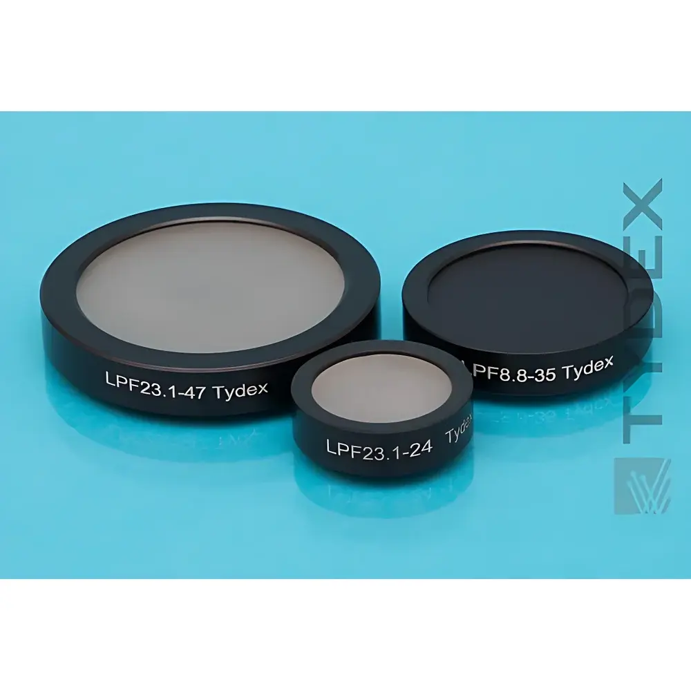
Tydex LPF Series Terahertz Low-Pass Optical Filters
| Brand | Tydex |
|---|---|
| Origin | Russia |
| Model | LPF |
| Component Category | Optical Element |
| Aperture Options | Standardized (e.g., 25.4 mm, 50.8 mm) |
| Cut-off Frequency Range | 0.1–3 THz (configurable per part number) |
| Transmission in Passband | >85% (typical, λ > λc) |
| Blocking in Stopband | <0.1% (typical, λ < λc) |
| Mounting | Precision Aluminum Ring Holder (C-Mount compatible) |
| Material Substrate | High-Resistivity Silicon (HR-Si), Polyethylene (PE), or Custom Dielectric Stacks |
| Surface Flatness | λ/10 @ 633 nm (per substrate) |
| Damage Threshold | ≥100 mW/cm² (CW), ≥0.1 J/cm² (pulsed, 100 fs–1 ps) |
Overview
Tydex LPF Series Terahertz Low-Pass Optical Filters are precision-engineered spectral control components designed for selective transmission of long-wavelength electromagnetic radiation while suppressing shorter-wavelength interference across the terahertz (THz) and far-infrared (FIR) regimes. These filters operate on the principle of controlled frequency-dependent attenuation—leveraging material dispersion, multi-layer interference, and substrate-based cutoff behavior rather than metallic mesh or resonant aperture structures. Unlike bandpass or notch filters, the LPF series provides monotonic spectral roll-off above a defined cut-off frequency (fc), enabling robust background suppression in broadband THz time-domain spectroscopy (TDS), continuous-wave (CW) imaging systems, and heterodyne receiver front-ends. Each filter is fabricated using high-purity, low-absorption substrates—including high-resistivity silicon (HR-Si) for 0.3–3 THz applications and ultra-high-molecular-weight polyethylene (UHMW-PE) for sub-0.3 THz operation—ensuring minimal phase distortion and thermal drift under laboratory and cryogenic conditions.
Key Features
- Configurable cut-off frequencies from 0.1 THz to 3.0 THz, designated by part number format LPF-fc–D (e.g., LPF-1.0-25.4 denotes 1.0 THz cut-off, 25.4 mm clear aperture)
- High in-band transmission (>85% average across passband) with minimal polarization dependence (<±3% variation over ±45° incidence)
- Effective stopband rejection: optical density ≥3 (transmission <0.1%) at wavelengths corresponding to frequencies ≥1.5×fc
- Mechanically stabilized mounting in black-anodized aluminum ring holders compliant with standard optomechanical interfaces (e.g., SM1, C-mount)
- Surface quality certified to λ/10 PV flatness (measured at 633 nm HeNe wavelength) and scratch-dig 20–10 per MIL-PRF-13830B
- Compatible with vacuum, dry nitrogen, and inert-gas purge environments; no outgassing observed per ASTM E595 testing
Sample Compatibility & Compliance
The LPF series supports diverse THz source and detector configurations—including photoconductive antennas (PCAs), bolometric arrays, Golay cells, and superconducting hot-electron bolometers (HEBs). All filters undergo spectral validation via Fourier-transform infrared (FTIR) spectrometry calibrated against NIST-traceable reference standards. Manufacturing adheres to ISO 9001:2015 quality management protocols, with documentation supporting GLP-compliant experimental reporting. While not FDA-regulated, design parameters align with ASTM E1423–21 (Standard Guide for Characterization of Terahertz Optical Components) and IEEE P3325 (Draft Standard for THz Instrumentation Interfaces). Each unit ships with a certificate of conformance listing measured spectral curves, surface metrology reports, and environmental handling guidelines.
Software & Data Management
No embedded firmware or proprietary software is required—LPF filters are passive optical elements. However, spectral performance data (transmission vs. frequency) is delivered in standardized ASCII format (.txt) and MATLAB-compatible .mat files, enabling direct integration into instrument control frameworks such as LabVIEW, Python (NumPy/SciPy), or MATLAB-based THz analysis pipelines. Users may import these datasets into commercial optical simulation tools (e.g., COMSOL Multiphysics Wave Optics Module or Lumerical MODE) for system-level modeling of beam propagation, étendue matching, and stray-light analysis. Audit trails for calibration data are maintained per ISO/IEC 17025 requirements for accredited laboratories performing THz metrology.
Applications
- THz Time-Domain Spectroscopy (TDS): Suppression of residual near-infrared pump leakage and parasitic 800-nm/1550-nm artifacts in electro-optic sampling setups
- Astronomical Instrumentation: Front-end filtering in ground-based submillimeter telescopes (e.g., ALMA Band 10 receivers) and balloon-borne FIR observatories requiring cryogenic stability
- Non-Destructive Testing (NDT): Enhancing contrast in THz pulsed imaging of polymer composites, pharmaceutical tablet coatings, and aerospace foam insulation
- Quantum Cascade Laser (QCL) Systems: Harmonic suppression and mode isolation in multi-frequency CW THz sources
- Material Characterization: Enabling accurate complex refractive index extraction in reflection-mode THz ellipsometry by eliminating broadband detector saturation
- Sensor Integration: Optimizing signal-to-noise ratio in uncooled microbolometer arrays operating below 1 THz
FAQ
What defines the cut-off frequency for a given LPF filter?
The cut-off frequency (fc) is empirically determined as the frequency at which measured transmission drops to 50% of its maximum passband value, verified under collimated, normal-incidence illumination using a calibrated THz-TDS system.
Can LPF filters be used at cryogenic temperatures?
Yes—HR-Si variants are qualified for operation down to 4 K; thermal contraction coefficients are matched between substrate and mount to minimize stress-induced wavefront error.
Is angle-of-incidence sensitivity characterized?
Yes—transmission curves are provided for 0°, 10°, and 20° incidence; angular tolerance for ≤5% passband shift is ±8° for fc ≥ 1 THz.
Do LPF filters require anti-reflection coating?
No—substrate selection and thickness optimization inherently minimize Fresnel reflections; measured reflectance remains <4% per surface across the passband.
How is spectral calibration traceability established?
Each batch is validated against a master reference filter calibrated at the PTB (Physikalisch-Technische Bundesanstalt) THz Metrology Lab, with uncertainty budgets reported per GUM (Guide to the Expression of Uncertainty in Measurement).