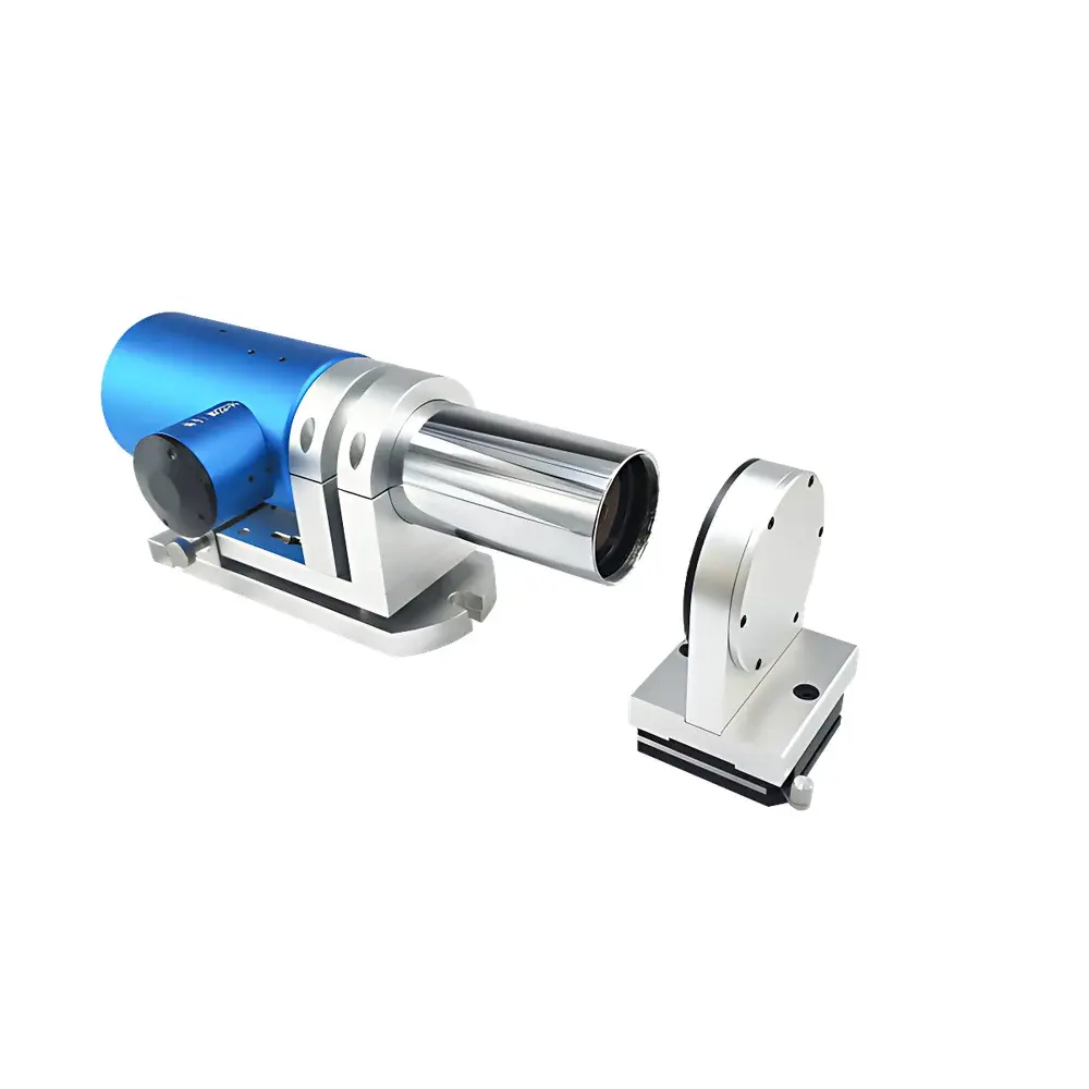


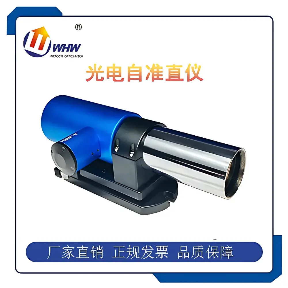
YANRUN MC030-MAT200/48/0.5 Dual-Axis Photoelectric Autocollimator
| Focal Length | 200 mm |
|---|---|
| Aperture | 48 mm |
| Light Source | Imported Semiconductor LED |
| Measurement Range | 0–20 m |
| Detector | High-Precision Photodetector |
| Display Resolution | Adjustable from 1″ to 0.0001″ (arc sec) |
| Field of View (X/Y) | 3200″ × 2400″ (arc sec) |
| Accuracy (Center) | ±0.5″ (0–±100″), ±1″ (0–±1000″) |
| Frequency Response | ≤30 Hz |
| Interface | USB 2.0 |
| Dimensions | 296 × 115 × 125 mm |
| Weight | 4.0 kg |
| Operating System | Windows 7 or later, 64-bit |
| Minimum CPU | 4th-gen Intel Core i3, ≥2.3 GHz |
Overview
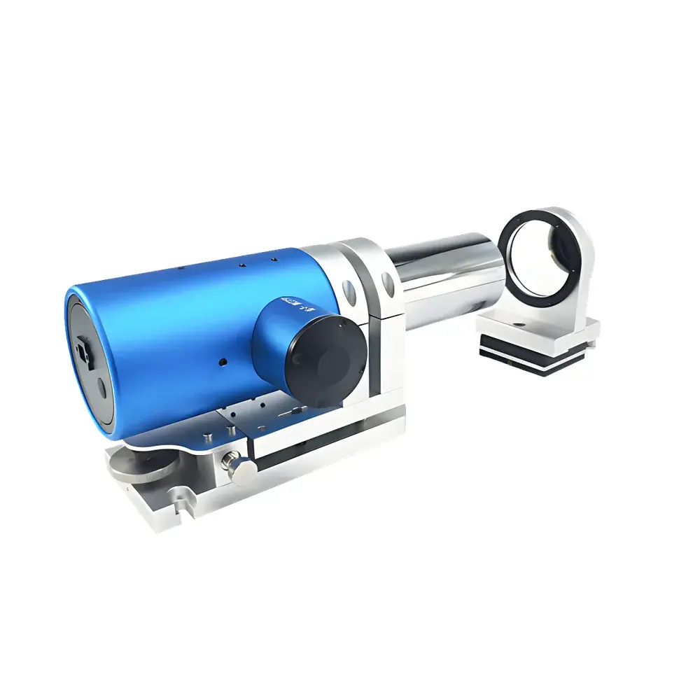
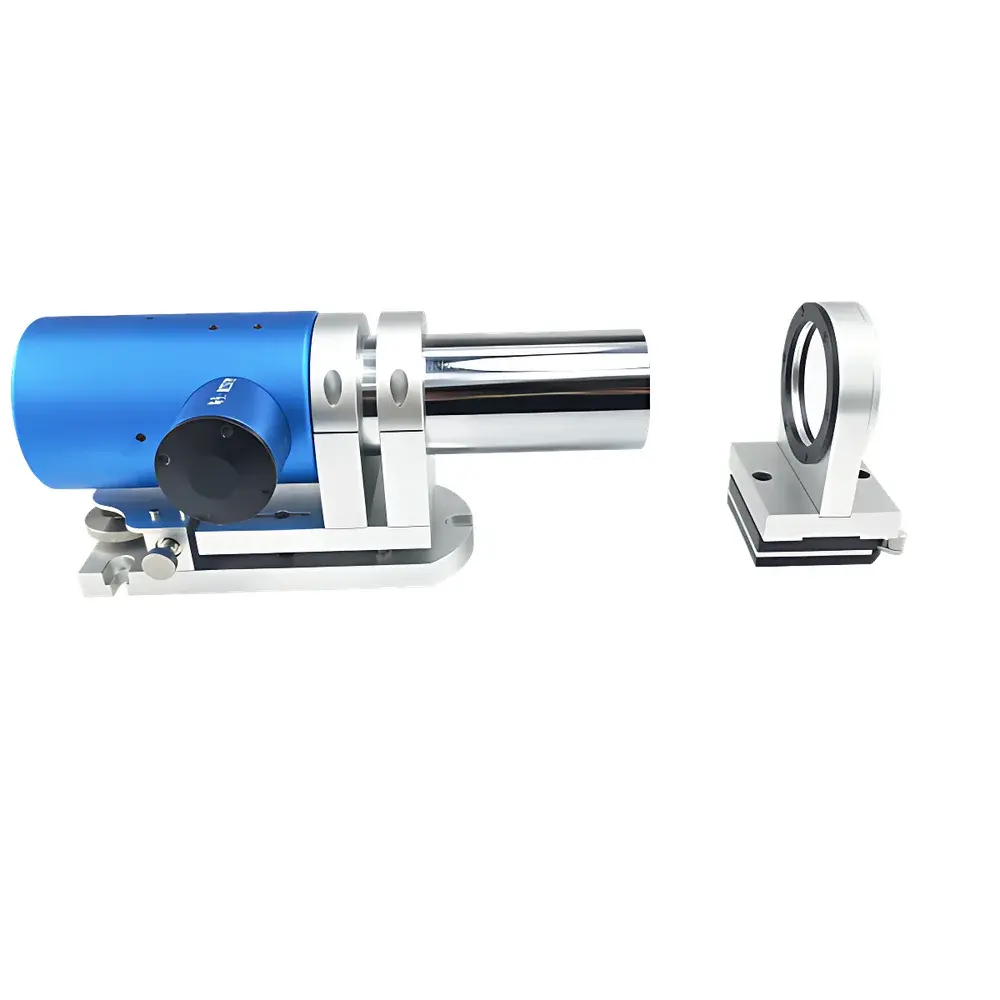
The YANRUN MC030-MAT200/48/0.5 Dual-Axis Photoelectric Autocollimator is a precision angular metrology instrument engineered for high-reproducibility measurement of minute angular deviations in two orthogonal axes (X and Y). It operates on the fundamental principle of optical autocollimation: a collimated beam—generated by projecting a reticle located at the focal plane of a 200 mm focal-length objective lens—is reflected back by a planar mirror placed normal to the optical axis. When the mirror rotates by an angle α, the returning beam undergoes a lateral displacement ΔS on the detector plane, corresponding to a total angular deviation of 2α. This displacement is captured by a high-resolution photodetector array and converted into arc-second angular values with traceable linearity. Unlike traditional visual autocollimators requiring subjective eyepiece alignment, this instrument replaces the ocular system with a digital imaging sensor and real-time centroid calculation algorithms—eliminating parallax and observer-dependent bias. Its compact monolithic design (296 × 115 × 125 mm, 4.0 kg), integrated long-life LED illumination, and USB 2.0 interface enable deployment in production floors, calibration labs, and field metrology environments without sacrificing laboratory-grade performance.
Key Features
- Dual-axis simultaneous acquisition: Independent X- and Y-direction angular measurements performed in parallel with synchronized sampling up to 30 Hz.
- Adjustable angular resolution: Configurable display resolution from 1″ down to 0.0001″ (arc second), supporting both routine verification and ultra-high-precision alignment tasks.
- Real-time electronic reticle imaging: On-screen visualization of reflected crosshair image with dynamic centroid tracking—enabling immediate visual confirmation of alignment status and drift behavior.
- Thermally stable LED illumination: Imported semiconductor light source with >50,000-hour service life and minimal spectral drift over time, ensuring consistent signal-to-noise ratio across extended operation cycles.
- Modular software architecture: Measurement engine supports plug-in analysis modules for straightness, flatness, perpendicularity, parallelism, and rotary table wobble evaluation—all compliant with ISO 230-1, ISO 10360, and ASME B89.3.7 standards.
- Multi-language UI: Native support for English, Chinese, Russian, and Korean interfaces—facilitating global deployment and multi-site metrology coordination.
- Export-ready data handling: Automated generation of standardized Excel reports (XLSX) with timestamped metadata, statistical summaries (mean, std dev, max/min), and pass/fail thresholds per user-defined tolerances.
Sample Compatibility & Compliance
The MC030-MAT200/48/0.5 is compatible with standard optical flats (λ/20 or better), kinematic mirror mounts, and custom retroreflective targets used in machine tool calibration, optical bench alignment, and inertial sensor testing. Its 48 mm clear aperture and 20 m maximum working distance accommodate large-scale industrial setups—including CNC gantry systems, coordinate measuring machine (CMM) guideways, and telescope optical benches. The instrument complies with electromagnetic compatibility (EMC) requirements per IEC 61326-1 and meets safety standards under IEC 61010-1 for laboratory electrical equipment. While not certified to FDA 21 CFR Part 11 out-of-the-box, its software architecture supports audit trail logging, user access control, and electronic signature integration when deployed in GLP/GMP-regulated environments (e.g., aerospace component qualification labs or medical device manufacturing QC).
Software & Data Management
Control and analysis are executed via a Windows-native application (64-bit, Win7+ required) that communicates with the instrument through a USB 2.0 interface. The software implements deterministic real-time acquisition scheduling to maintain ≤30 Hz frame rate stability under full-resolution mode. Raw pixel coordinates from the photodetector are processed using sub-pixel centroid interpolation (Gaussian-weighted moment method) to achieve <0.001″ repeatability under controlled thermal conditions. All measurement sessions are stored in a structured binary format (.ymd) containing raw image frames, environmental timestamps, hardware configuration snapshots, and operator annotations. Export functions include CSV for third-party statistical analysis, PDF for formal calibration records, and XML for integration with enterprise MES/QMS platforms. Optional add-ons provide FFT-based vibration spectrum analysis, thermal drift compensation models, and automated ISO 1101 geometric tolerance reporting.
Applications
- Precision machine tool installation: Angular verification of linear axes, spindle tilt, and slideway squareness per ISO 230-1 Annex C.
- Aerospace component assembly: Alignment of optical benches, inertial navigation platform leveling, and satellite payload pointing verification.
- Optical fabrication QC: Centering error assessment of lenses and prisms, wedge angle measurement of interferometric cavities, and collimation validation of laser resonators.
- Research instrumentation: Calibration of goniometers, characterization of piezoelectric stage hysteresis, and dynamic angular response testing of MEMS mirrors.
- Calibration laboratory use: Transfer standard for angle artifact verification (e.g., polygon mirrors, angle blocks) traceable to NIM or PTB national standards.
FAQ
What is the recommended warm-up time before high-accuracy measurements?
For measurements requiring ≤0.5″ uncertainty, power-on stabilization for ≥15 minutes is mandatory. For metrological certification (e.g., ISO/IEC 17025 accredited calibration), the unit must be thermally equilibrated in a temperature-controlled environment (±0.5 °C) for ≥24 hours prior to verification.
Does the instrument require periodic recalibration?
Yes. Annual recalibration against a certified angle standard (e.g., NIST-traceable autocollimator or angle block set) is recommended. Internal self-check routines verify LED intensity, detector linearity, and optical centering during startup.
Can the system measure dynamic angular motion?
Yes—up to 30 Hz bandwidth enables capture of low-frequency oscillations such as thermal drift, servo jitter, or mechanical resonance modes in rotating assemblies.
Is third-party software integration supported?
The SDK provides documented DLL APIs and LabVIEW/VB.NET/C# examples for embedding measurement logic into custom automation frameworks. Raw pixel data streaming is accessible via memory-mapped I/O.
What environmental conditions affect measurement accuracy?
Air turbulence (especially near heat sources), vibration (≥0.5 µm RMS at 10–100 Hz), and ambient light saturation (>100 lux on detector surface) degrade resolution. Use in air-conditioned rooms (20 ± 1 °C) with optical isolation tables yields optimal results.


