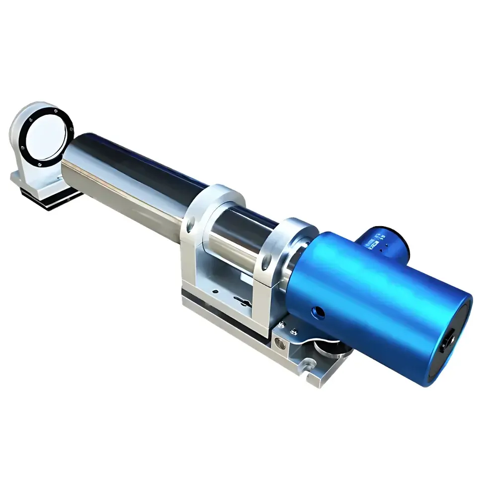
YANRUN MC030-YRMCT400/68/0.3 Dual-Axis Photoelectric Autocollimator
| Brand | YANRUN |
|---|---|
| Origin | Shanghai, China |
| Manufacturer Type | Manufacturer |
| Model | MC030-YRMCT400/68/0.3 |
| Focal Length | 400 mm |
| Aperture Diameter | 68 mm |
| Light Source | High-Stability Semiconductor LED |
| Measurement Range | 0–50 m |
| Angular Resolution | Adjustable down to 0.0001″ (arc second) |
| Field of View (X/Y) | 1700″ × 1350″ (arc seconds) |
| Accuracy (Center) | ±0.3″ (0–±100″), ±0.5″ (0–±600″) |
| Sampling Frequency | ≤30 Hz |
| Interface | USB 2.0 |
| Dimensions | 490 × 135 × 125 mm (L×W×H) |
| Weight | 7.2 kg |
| Operating System | Windows 7 or later (64-bit) |
| Minimum CPU | Intel Core i3-4th Gen, ≥2.3 GHz |
Overview
The YANRUN MC030-YRMCT400/68/0.3 Dual-Axis Photoelectric Autocollimator is a precision angular metrology instrument engineered for high-reproducibility measurement of minute angular deviations in two orthogonal axes (X and Y) simultaneously. It operates on the fundamental principle of optical autocollimation: a collimated beam—generated by projecting a reticle located at the focal plane of a 400 mm focal length objective lens—is reflected off a planar mirror and reimaged onto a high-resolution photodetector array situated at the same focal plane. When the mirror rotates by angle α, the returned image shifts by ΔS ≈ 2α·f (where f = 400 mm), enabling sub-arcsecond angular quantification via pixel-level centroid detection. This non-contact, drift-compensated methodology eliminates human parallax error inherent in traditional visual autocollimators and supports traceable calibration against national standards. Designed for integration into metrology workflows requiring ISO/IEC 17025-compliant uncertainty budgets, the system delivers stable performance under controlled laboratory conditions and meets typical requirements for alignment verification in high-precision mechanical assembly, optical bench setup, and coordinate measuring machine (CMM) calibration.
Key Features
- Dual-axis simultaneous acquisition with real-time digital imaging—eliminates sequential scanning delays and cross-axis coupling errors
- High-stability semiconductor LED illumination with >50,000-hour lifetime, ensuring consistent intensity and spectral stability without thermal drift
- Adjustable angular resolution from 1″ down to 0.0001″ (arc second), configurable per application demand and environmental constraints
- Integrated electronic eyepiece interface with live centroid tracking, supporting dynamic alignment monitoring at up to 30 Hz frame rate
- Modular mechanical architecture: includes precision two-axis tilt base, interchangeable mirrors, and standardized mounting interfaces (M6/M8 threaded holes)
- USB 2.0 host communication with deterministic latency; driver-free operation under Windows 7+ (64-bit); compatible with standard industrial PCs meeting minimum i3-4th Gen specifications
- Onboard firmware with built-in self-diagnostic routines, including sensor dark-current compensation and optical path alignment validation
Sample Compatibility & Compliance
The MC030-YRMCT400/68/0.3 is optimized for use with flat, specularly reflective surfaces—such as optical flats, kinematic mounts, and precision-ground mirror substrates—with reflectivity ≥85% in the visible spectrum (450–650 nm). It complies with dimensional stability requirements outlined in ISO 10110-7 for optical component testing and supports measurement protocols referenced in ASTM E1393 (Standard Practice for Alignment of Optical Systems) and ISO 230-1 (Test Code for Machine Tools – Part 1: Geometric Accuracy). While not certified to FDA 21 CFR Part 11, its software architecture supports audit-trail logging and user-access controls suitable for GLP/GMP-aligned environments when deployed with validated IT infrastructure. Calibration certificates are issued per JJG 814–2015 (Chinese National Metrological Verification Regulation for Autocollimators) and may be supplemented with NIST-traceable reports upon request.
Software & Data Management
The included Windows-based control software provides real-time visualization of the reflected reticle image, automatic centroid calculation, and multi-point statistical analysis. It supports export of raw pixel coordinates, angular deviation vectors, and time-series datasets in CSV and Excel (.xlsx) formats—fully compliant with internal QA documentation systems. Advanced modules enable straightness profiling (via sequential position sampling), perpendicularity assessment (using dual-mirror reversal technique), and plane flatness evaluation (through grid-based point cloud generation). All measurement sessions record metadata—including timestamp, ambient temperature, operator ID, and instrument configuration—enabling full traceability. The software adheres to IEC 62304 Class B software lifecycle requirements for medical device-adjacent applications and includes configurable report templates aligned with ISO/IEC 17025 clause 7.8.2.
Applications
- Precision alignment of CNC machine tool spindles, linear guides, and rotary tables
- Verification of orthogonality and squareness in multi-axis motion platforms used in semiconductor lithography equipment
- Calibration of angular encoders and inertial reference units in aerospace test benches
- In-process monitoring of mirror tilt stability during vacuum-coating processes in optical fabrication facilities
- Characterization of thermal drift in optomechanical assemblies under controlled environmental chambers
- Education and research in undergraduate and graduate optics laboratories—supporting pedagogical experiments in wavefront sensing and interferometric alignment
FAQ
What is the recommended warm-up time before high-accuracy measurements?
A minimum preheating period of 15 minutes is required to stabilize thermal gradients across the optical path and detector array. For metrological-grade verification (e.g., calibration lab use), the instrument must be thermally equilibrated in a 20 ± 0.5 °C environment for ≥24 hours prior to measurement.
Can this autocollimator measure angular displacement over long distances?
Yes—the system maintains specified accuracy up to 50 meters, provided atmospheric turbulence is minimized (e.g., indoor controlled environments or laminar airflow enclosures) and the target mirror surface roughness remains below λ/10 (RMS) at 633 nm.
Is third-party software integration supported?
The device exposes a documented DLL API and SCPI-like command set over USB, enabling integration with LabVIEW, MATLAB, Python (via PyUSB), and custom C++/C# applications. No proprietary runtime dependencies are imposed.
How is traceability ensured for calibration?
Each unit ships with a factory calibration certificate referencing a primary standard autocollimator calibrated against a NPL-traceable angle comparator. Users may perform intermediate verification using certified right-angle prisms or autocollimation cubes per ISO 10110-7 Annex D.
Does the system support automated pass/fail decision logic?
Yes—the software allows definition of tolerance bands per axis, with configurable alarms, color-coded visualization, and automated pass/fail flagging in exported reports—suitable for SPC-driven production line deployment.


