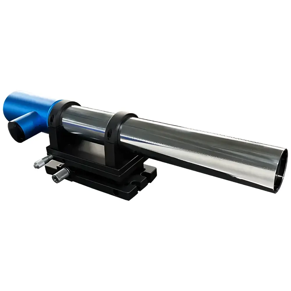
YANRUN MC030-ZJUH5000/0.2 Photoelectric Autocollimator
| Brand | YANRUN |
|---|---|
| Origin | Shanghai, China |
| Manufacturer Type | Manufacturer |
| Model | MC030-ZJUH5000/0.2 |
| Dimensions | 580 × 140 × 140 mm |
Overview
The YANRUN MC030-ZJUH5000/0.2 is a high-precision photoelectric autocollimator engineered for non-contact angular metrology in industrial metrology labs, precision assembly lines, and optical R&D facilities. It operates on the fundamental principle of optical autocollimation: a collimated beam—generated by projecting a reticle located at the focal plane of a high-stability objective lens—is directed toward a reflective surface (e.g., a mirror or polished workpiece). When the reflector tilts by angle α, the returning beam undergoes a 2α angular deviation, resulting in a linear displacement ΔS on a calibrated photodetector array positioned at the same focal plane. This displacement is measured with sub-pixel resolution, enabling angular measurement resolution down to 0.2 arcseconds (as indicated by the “/0.2” suffix), consistent with ISO 10110-5 and VDI/VDE 2634 Part 2 standards for angular metrology systems.
Key Features
- Simultaneous dual-axis (X and Y) angular measurement with real-time digital readout, eliminating sequential alignment steps and reducing cumulative setup uncertainty.
- Integrated electronic eyepiece with live video feed and on-screen crosshair overlay—replacing subjective visual alignment and minimizing operator-induced parallax and targeting errors.
- High-resolution linear CCD/CMOS photodetector array optimized for centroid-based displacement calculation, delivering stable signal-to-noise ratio across environmental temperature fluctuations (15–30 °C operational range).
- Long-life, thermally stabilized LED light source with narrow spectral bandwidth (635 nm ±5 nm), ensuring consistent illumination intensity and minimal drift over >10,000 hours of continuous operation.
- Modular optical interface supporting interchangeable retroreflective targets, wedge prisms, and extended-range adapters—enabling configuration flexibility for applications from small-optic alignment to large-scale machine tool calibration.
- Embedded firmware with multi-language UI (English, Chinese, Russian, Korean) compliant with IEC 62366-1 usability engineering requirements for medical and industrial instrumentation.
Sample Compatibility & Compliance
The MC030-ZJUH5000/0.2 is compatible with any optically flat, specularly reflective surface ≥Φ10 mm, including fused silica mirrors, stainless steel reference flats, silicon wafers, and coated optical components. It supports both static and quasi-dynamic angular monitoring (up to 10 Hz sampling under triggered acquisition mode). The instrument conforms to electromagnetic compatibility per EN 61326-1:2013 and safety requirements per EN 61010-1:2010. Measurement traceability is maintained via internal calibration routines aligned to NIST-traceable angular artifacts; full calibration certificates (including uncertainty budgets per GUM) are available upon request. Data integrity meets GLP/GMP documentation requirements through optional audit-trail-enabled firmware (compliant with FDA 21 CFR Part 11 Annex 11 principles).
Software & Data Management
The included YANRUN AutoCal Studio software (v4.2+) provides comprehensive data acquisition, analysis, and reporting functionality. It supports real-time curve plotting, automatic best-fit line and plane generation, error band visualization (per ISO 230-1/ISO 230-6), and statistical process control (SPC) charting. All raw displacement values, computed angles, timestamps, and environmental metadata (ambient temperature, humidity if external sensor connected) are stored in structured binary format (.yac) with lossless compression. Export options include ANSI-compliant CSV, Excel (.xlsx) with embedded formulas and formatting, PDF reports with digital signature fields, and XML for integration into MES or LIMS platforms. Batch processing scripts allow automated evaluation of multi-point alignment sequences—critical for aerospace component verification workflows.
Applications
- Precision alignment of CNC machine tool spindles, linear guideways, and rotary tables—supporting ISO 230-1 geometric accuracy verification.
- Verification of straightness, flatness, perpendicularity, and parallelism in structural frames, optical benches, and semiconductor lithography stages.
- Dynamic tilt monitoring of high-precision rotation stages used in synchrotron beamline instrumentation and adaptive optics systems.
- Assembly and adjustment of laser cavities, interferometer arms, and fiber-optic coupling platforms requiring sub-arcsecond repeatability.
- Teaching and research in university physics and optical engineering laboratories—fully documented measurement protocols align with AAPT and OSA pedagogical guidelines.
FAQ
What is the angular resolution and measurement range of the MC030-ZJUH5000/0.2?
The instrument achieves ≤0.2 arcsecond resolution over a ±1000 arcsecond (±0.278°) full-scale range in standard configuration. Extended-range modes (via optional beam-splitting modules) support up to ±5000 arcseconds.
Does it require external calibration references?
No—internal self-calibration routines correct for detector nonlinearity and optical axis drift using built-in reference patterns. However, periodic verification against traceable angular standards (e.g., NIST SRM 2089a) is recommended annually per ISO/IEC 17025.
Can it interface with PLCs or industrial automation systems?
Yes—RS-232, USB-CDC, and Ethernet (TCP/IP Modbus TCP) communication interfaces are supported. SDKs for C++, Python, and LabVIEW enable OEM integration into factory-floor control architectures.
Is the LED light source replaceable in the field?
The LED module is soldered onto the optical engine PCB and not user-replaceable; however, its rated lifetime exceeds 10,000 hours under nominal operating conditions, and warranty coverage includes source replacement if luminance degradation exceeds 15% within 3 years.
How is thermal drift compensated during long-duration measurements?
The system employs dual-sensor thermal monitoring (objective lens housing + detector substrate) and applies real-time gain/offset correction based on empirically derived thermal coefficient models—validated across 15–30 °C ambient ranges per ISO 10012-1.