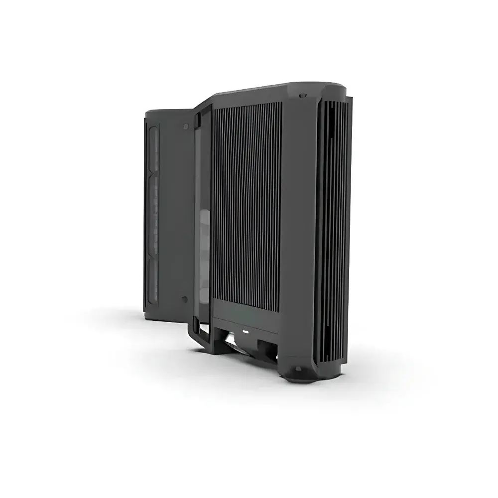
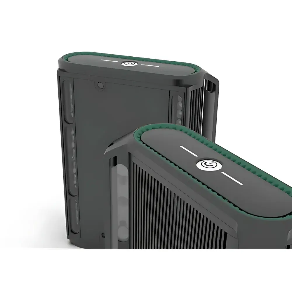
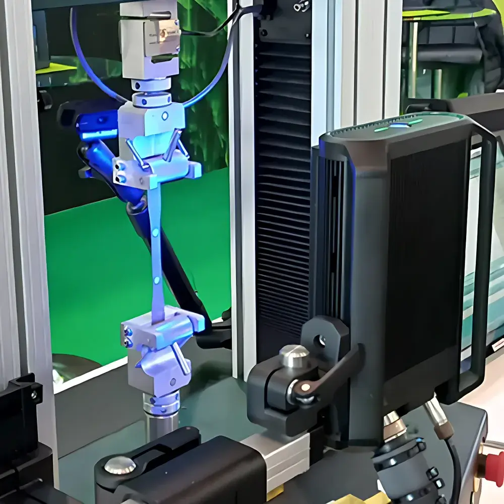
Tinius Olsen Vector U200 Non-Contact Optical Extensometer
| Brand | Tinius Olsen |
|---|---|
| Origin | USA |
| Model | Vector U200 |
| Field of View (FOV) | 200 mm |
| Gauge Length Range | 25–180 mm (longitudinal) |
| Resolution | 0.5 µm |
| Compliance | ISO 9513 Class 0.2 / ASTM E83 Class B1 |
| Output Options | Analog (±10 V) and/or Serial Digital (RS-232/RS-485, ASCII or Modbus RTU) |
| Dimensions | 200 × 70 × 250 mm (W × H × D) |
| Marking Modes | Dot, Ring, Line, Spot, Edge Tracking, Surface Tracking |
Overview
The Tinius Olsen Vector U200 is a high-precision, non-contact optical extensometer engineered for accurate longitudinal strain measurement during uniaxial tensile, compression, and cyclic mechanical testing. Utilizing digital image correlation (DIC)-based edge detection and sub-pixel centroid tracking algorithms, the Vector U200 captures real-time displacement data without physical contact—eliminating loading artifacts, inertia effects, or specimen surface interference. Its 200 mm field of view enables flexible gauge length configuration from 25 mm to 180 mm, supporting standardized test protocols across metallic alloys, polymers, composites, elastomers, and thin-film substrates. Designed for integration with universal testing machines (UTMs), the system operates independently of crosshead motion and delivers traceable, metrologically validated strain data compliant with international standards for extensometry.
Key Features
- Non-contact optical measurement using high-resolution monochrome CMOS imaging and adaptive LED illumination for consistent contrast across diverse material surfaces (matte, reflective, textured, or coated)
- Sub-pixel resolution of 0.5 µm (1.9685 × 10⁻⁵ in), enabling detection of micro-strain events and precise yield point identification
- Configurable marking strategies—including discrete dot, concentric ring, linear segment, and stochastic spot patterns—optimized for low-contrast or optically challenging specimens
- Real-time edge and surface tracking algorithms that dynamically compensate for specimen drift, rotation, or out-of-plane motion during testing
- Dual-output architecture supporting simultaneous analog voltage output (±10 V, fully isolated) and serial digital communication (RS-232/RS-485) with ASCII or Modbus RTU protocol for PLC and SCADA interoperability
- Compact form factor (200 × 70 × 250 mm) with integrated mounting brackets compatible with standard UTM crossheads and side frames
- Firmware-upgradable architecture with embedded diagnostics, self-calibration routines, and configurable sampling rates up to 1 kHz
Sample Compatibility & Compliance
The Vector U200 accommodates a broad spectrum of specimen geometries and surface characteristics without requiring speckle patterning or surface preparation. Its adaptive illumination and multi-threshold segmentation engine support reliable tracking on bare metals, anodized aluminum, painted steel, injection-molded thermoplastics, fiber-reinforced laminates, and rubber compounds. Calibration is performed per ISO 9513:2012 Annex A using certified reference artifacts, ensuring Class 0.2 accuracy over the full gauge length range. For dynamic and high-temperature applications, optional thermal shielding and synchronized external triggering are available. The system meets ASTM E83-22 Class B1 requirements for verification of extensometer performance under static and quasi-static loading conditions. All calibration records, firmware logs, and user-configured parameters are stored internally with timestamped audit trails, supporting GLP/GMP environments and FDA 21 CFR Part 11 compliance when deployed with validated software interfaces.
Software & Data Management
The Vector U200 operates as a standalone sensor node but integrates seamlessly with industry-standard test control platforms—including Tinius Olsen Horizon™, MTS TestSuite™, Instron Bluehill®, and custom LabVIEW or Python-based acquisition systems. Native drivers provide real-time streaming of displacement, strain, and velocity data with nanosecond-level time stamping. Raw image metadata (exposure time, gain, region-of-interest coordinates) is embedded in each data packet for post-hoc uncertainty analysis. Configuration and diagnostics are managed via a browser-based HTML5 interface accessible over Ethernet, eliminating proprietary software dependencies. Data export supports CSV, HDF5, and XML formats with SI-unit annotation and metadata tagging per ASTM E1434. Firmware updates are delivered via secure HTTPS with SHA-256 signature verification.
Applications
- Tensile testing per ISO 6892-1, ASTM E8, and ASTM D638 for modulus, yield strength, ultimate tensile strength, and elongation at break
- Cyclic fatigue characterization including hysteresis loop analysis and ratcheting behavior in metallic and polymeric systems
- Creep and stress-relaxation studies requiring long-duration, drift-compensated strain monitoring
- Adhesive bond line deformation analysis and interfacial shear strain mapping in lap-shear configurations
- Validation of finite element models through direct comparison of experimental strain fields and simulated nodal displacements
- Quality assurance in aerospace component certification (e.g., AMS 2358, NADCAP AC7101) and automotive material qualification (e.g., VW PV 1004, GMW 14124)
FAQ
Does the Vector U200 require speckle pattern application on specimens?
No. The system employs contrast-based edge detection and surface texture tracking; speckling is optional and only recommended for highly specular or uniformly colored surfaces where natural texture is insufficient.
Can it be used in elevated temperature environments?
Yes—when equipped with the optional thermal shroud accessory (operating range up to 200 °C) and synchronized with furnace-compatible test fixtures.
Is ISO 9513 calibration traceable to NIST or equivalent NMIs?
Yes. Factory calibration uses NIST-traceable step gauges and laser interferometer validation; certificates include uncertainty budgets per GUM (JCGM 100:2008).
What is the maximum sampling rate for real-time data streaming?
Up to 1,000 Hz with full-resolution displacement output; reduced ROI modes enable higher frame rates for specialized high-speed applications.
How is system verification performed between calibrations?
Built-in self-test includes geometric distortion mapping, lens focus validation, and pixel response uniformity checks—automatically executed at power-on and configurable for scheduled intervals.


