Inframet MS Series Multi-Sensor Test System
| Brand | Inframet |
|---|---|
| Origin | Poland |
| Model | MS |
| Aperture Options | 100–600 mm (selectable) |
| Spectral Coverage | VIS, NIR, SWIR, MWIR, LWIR |
| Measurement Capabilities | MRTD, MTF, SiTF, NETD, FPN, Non-Uniformity, FOV, Distortion, Magnification, Response Function, 3D Noise, Bad Pixels, PVF, SNR, TOD, NEFD, MDTD, NER, NEP, ATF, NEI, D* |
| Alignment Functions | Co-boresighting of thermal imagers, VIS/NIR/SWIR cameras, and laser systems (rangefinders, designators, illuminators) |
| Imaging Interface Options | Analog (PAL/NTSC), Camera Link, GigE Vision, LVDS, USB 2.0 |
| Compliance | Designed for ASTM E1213, ISO 12233, ISO 18844, MIL-STD-3009, and GLP/GMP-aligned test workflows |
Overview
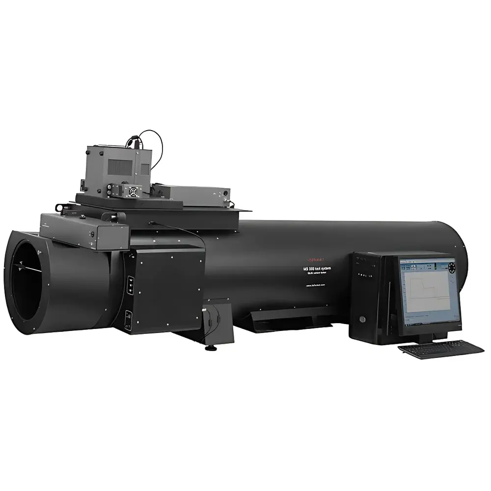
The Inframet MS Series Multi-Sensor Test System is a high-precision, modular optical metrology platform engineered for comprehensive performance characterization and co-boresight alignment of multi-spectral electro-optical (EO) and infrared (IR) imaging systems. Based on the principles of calibrated projection-based image analysis, the system integrates collimated optical stimulus generation with traceable radiometric sources and automated image evaluation algorithms to quantify both radiometric and geometric performance parameters across visible (VIS), near-infrared (NIR), short-wave infrared (SWIR), mid-wave infrared (MWIR), and long-wave infrared (LWIR) bands. Its architecture supports full-system testing—from single-band imagers to fused multi-sensor payloads—under controlled laboratory conditions compliant with international standards including ASTM E1213 (for thermal imager resolution), ISO 18844 (for boresight alignment uncertainty), and MIL-STD-3009 (for EO/IR sensor performance verification). The system is not a standalone camera or detector but a reference-grade test infrastructure used by R&D labs, defense calibration centers, and quality assurance departments to validate design specifications, support production acceptance testing, and ensure interoperability in multi-sensor platforms.
Key Features
- Multi-band stimulus generation: Interchangeable CDT off-axis reflective collimators (apertures from 100 mm to 600 mm) paired with spectral-specific radiation sources—including TCB differential blackbodies (MWIR/LWIR), broadband VIS/NIR lamps, SWIR-optimized halogen or LED sources, and MTB blackbodies—enabling traceable irradiance and radiance calibration per band.
- Automated parametric measurement suite: Fully software-controlled acquisition and analysis of 25+ standardized metrics including Minimum Resolvable Temperature Difference (MRTD), Modulation Transfer Function (MTF), Signal Transfer Function (SiTF), Noise-Equivalent Temperature Difference (NETD), Fixed Pattern Noise (FPN), spatial non-uniformity, field-of-view (FOV), geometric distortion, magnification, temporal and spatial noise spectra (3D noise), bad pixel maps, Peak-to-Valley Flatness (PVF), Signal-to-Noise Ratio (SNR), Triangle Orientation Discrimination (TOD), and detector-specific figures of merit (D*, NEP, NER, NEFD, NEI).
- Co-boresight alignment engine: Motorized, six-degree-of-freedom positioning stage combined with real-time centroid tracking enables quantitative angular deviation measurement between optical axes of heterogeneous sensors—e.g., thermal imager vs. VIS camera, SWIR camera vs. laser rangefinder—within ±1 arcsecond repeatability.
- Flexible imaging interface support: Hardware-compatible with analog video (PAL/NTSC), digital interfaces (Camera Link, GigE Vision, LVDS, USB 2.0), and frame grabbers optimized for both legacy analog outputs (≤756×576 @ 25 Hz) and modern high-resolution, high-frame-rate digital sensors.
- Modular target library: Standardized, NIST-traceable target sets—including USAF 1951, Siemens star, slanted-edge, bar patterns, uniformity fields, and laser spot arrays—available in material- and coating-optimized variants for each spectral band (e.g., gold-coated for LWIR, MgF₂-coated for VIS).
Sample Compatibility & Compliance
The MS system accommodates a broad range of EO/IR hardware configurations: uncooled and cooled thermal imagers (microbolometer, InSb, HgCdTe), VIS/NIR TV cameras (CCD/CMOS), SWIR InGaAs focal plane arrays, laser rangefinders (eye-safe and non-eye-safe classes), laser designators, and integrated multi-sensor gimbals. All measurements adhere to metrological best practices defined in ISO/IEC 17025-accredited environments. Software audit trails, electronic signatures, and configurable report templates support FDA 21 CFR Part 11 compliance for regulated industries. Calibration certificates for collimators, blackbodies, and reference targets are provided with documented uncertainty budgets aligned to EURAMET cg-18 and NIST SP 250-95 guidelines.
Software & Data Management
The proprietary Inframet TestSuite™ software provides a unified GUI for instrument control, stimulus sequencing, image capture, parameter computation, and report generation. It features scriptable test sequences (Python API), batch processing for production-line throughput, version-controlled configuration files, and export to CSV, XML, and PDF formats. Raw image data and metadata (exposure time, source temperature, collimator focus position, ambient conditions) are stored in hierarchical HDF5 archives. Integrated GLP-compliant electronic lab notebook functionality logs operator actions, calibration events, and system diagnostics with time-stamped, immutable records.
Applications
- Development validation of dual-band (e.g., MWIR + VIS) targeting pods for airborne platforms.
- Production line acceptance testing of thermal weapon sights per MIL-PRF-46374.
- Boresight drift monitoring during environmental stress screening (thermal cycling, vibration).
- Quantitative comparison of MTF degradation before/after optical cleaning or lens re-alignment.
- Verification of laser rangefinder emission axis alignment relative to imager line-of-sight in ground vehicle fire control systems.
- Characterization of non-uniformity correction algorithm efficacy using dynamic scene simulation.
FAQ
Does the MS system support automated MRTD measurement per ASTM E1213?
Yes. The system implements the observer-independent, threshold-based algorithm specified in ASTM E1213-21 using programmable triangle targets and adaptive contrast ramping.
Can it measure both NETD and NEP for cooled photon detectors?
Yes. NETD is derived from temporal noise and responsivity under blackbody illumination; NEP is calculated from measured noise-equivalent power at the cold stop plane using calibrated aperture-defined input flux.
Is third-party calibration of the collimator and blackbody included?
Each delivered system includes factory calibration certificates with uncertainties referenced to national standards; optional annual recalibration services are available via Inframet’s ISO/IEC 17025-accredited calibration lab.
What is the maximum frame rate supported for GigE Vision sensors?
Up to 120 fps at 1280×1024 (8-bit) with full ROI readout; sustained bandwidth depends on host PC NIC configuration and driver optimization.
How is laser beam divergence accounted for during boresight measurement?
The system uses a high-resolution laser-sensitive card (1 µm spatial resolution) and sub-pixel centroid fitting to determine beam center; divergence-induced spot size error is corrected using manufacturer-provided beam parameter product (BPP) data.