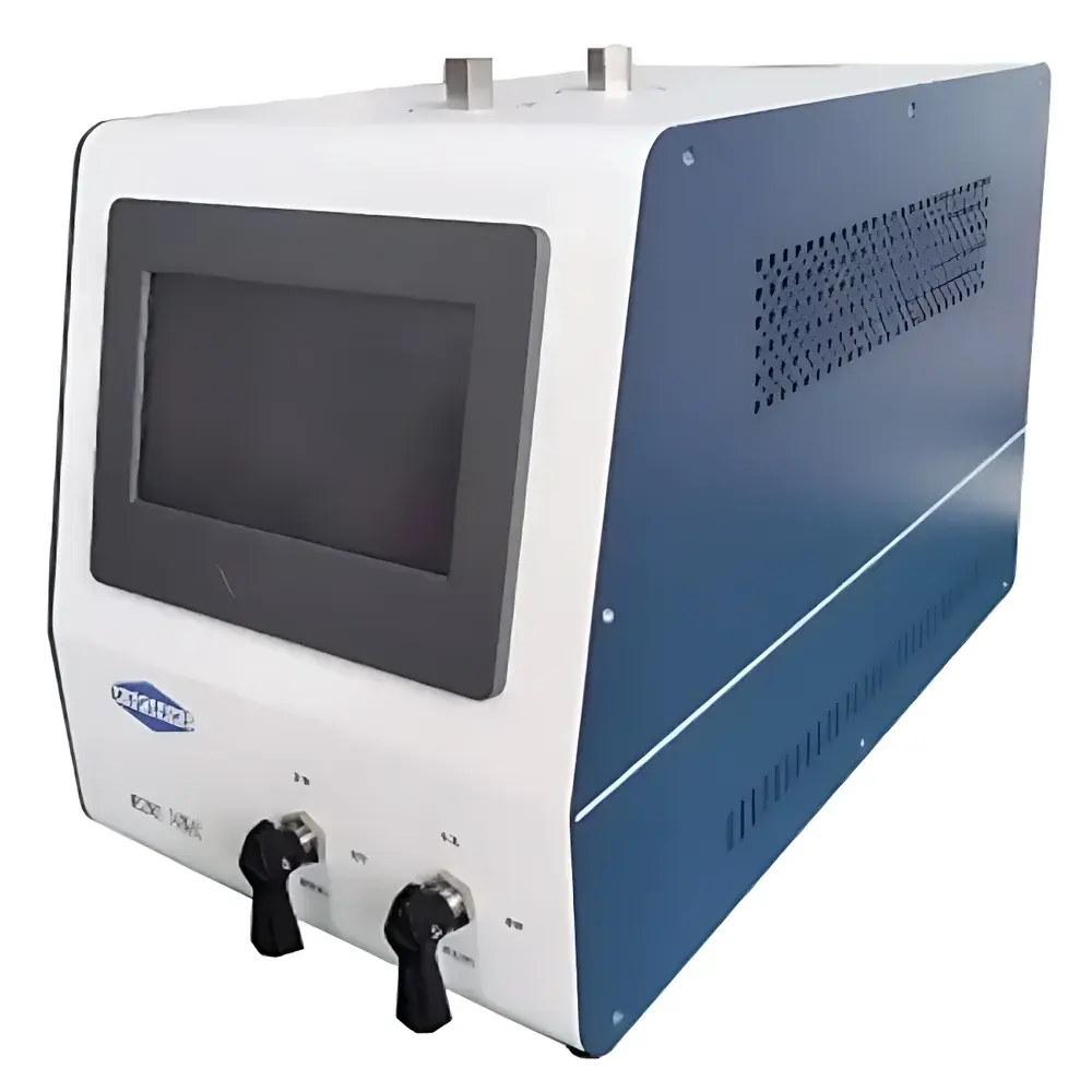
MS200S-II Dual-Channel Flash Vaporizer by MNK
| Brand | MNK |
|---|---|
| Origin | Beijing, China |
| Model | MS200S-II |
| Dimensions | 460 × 270 × 300 mm |
| Operating Liquid Inlet Pressure | 100–400 psi |
| Maximum Flash & Jacket Temperature | 230 °C |
| Temperature Control Accuracy | ±0.1 °C |
Overview
The MNK MS200S-II Dual-Channel Flash Vaporizer is an engineered sample introduction system designed specifically for the quantitative and reproducible vaporization of liquid hydrocarbon samples prior to gas chromatographic (GC) analysis. It operates on the principle of controlled flash vaporization—rapid phase transition from liquid to vapor under precisely regulated temperature and pressure conditions—ensuring stoichiometric preservation of C1–C5 hydrocarbon composition. Unlike simple heated transfer lines or manual vaporization setups, the MS200S-II maintains thermodynamic equilibrium during phase change, minimizing fractionation, adsorption losses, and cold-spot condensation. Its dual-channel architecture enables parallel processing of two pressurized sampling cylinders (e.g., DOT-4L or ASTM D1265-compliant cylinders), significantly improving laboratory throughput in routine refinery, petrochemical, and quality control workflows.
Key Features
- Dual independent vaporization channels with fully segregated thermal control loops—each channel features a dedicated flash chamber and heated transfer line, eliminating cross-contamination and enabling method-matched conditioning for dissimilar samples.
- High-fidelity temperature regulation: flash chamber and sample line jackets are independently controlled up to 230 °C with ±0.1 °C stability, verified per ASTM E220 calibration traceability protocols.
- M14×1.5 internal thread quick-connect inlets accommodate standard hydrocarbon sampling cylinders; optional adapters available for ISO 8573-9 or CGA V-7 compliant fittings upon request.
- Integrated sintered stainless steel particulate filter (5 µm retention) upstream of the vaporization zone prevents particulate-induced blockage and extends service intervals between maintenance cycles.
- Fail-safe pressure management: built-in spring-loaded relief valve activates at preset overpressure thresholds (factory-set to 600 psi, adjustable within 400–800 psi range) and vents directly to atmospheric vent line with flame arrestor option.
- Passivated 316L stainless steel flow path—including Swagelok®-style fittings and electropolished tubing—minimizes surface reactivity with sulfur-containing compounds (e.g., mercaptans, H2S), ensuring integrity of trace-level speciation data.
- Intuitive 7-inch resistive touchscreen HMI with embedded logic for sequence programming, real-time parameter logging, and alarm history storage (last 1,000 events).
Sample Compatibility & Compliance
The MS200S-II is validated for use with liquefied petroleum gas (LPG), light naphthas, cracked gasoline fractions, and other volatile hydrocarbon liquids conforming to ASTM D1265, ASTM D2593, and ISO 8573-5 specifications. It supports both saturated and unsaturated C1–C5 species—including methane, ethane, propane, butanes, isobutane, pentanes, ethylene, propylene, and butylenes—without catalytic decomposition or thermal cracking under nominal operating conditions. The instrument’s mechanical design complies with CE machinery directive 2006/42/EC and pressure equipment directive 2014/68/EU (PED Category I). All firmware and HMI logs support audit-trail generation required for GLP and GMP environments under FDA 21 CFR Part 11 when integrated with compliant LIMS platforms.
Software & Data Management
The embedded controller records timestamped operational parameters—including actual vs. setpoint temperatures, inlet pressure, valve actuation status, and fault codes—at 1 Hz resolution. Data export is supported via USB 2.0 (CSV format) or optional RS-485 Modbus RTU interface for integration into SCADA or laboratory automation systems. No proprietary software installation is required; configuration and diagnostics are performed entirely through the onboard HMI. System logs include automatic detection of thermal drift, pressure decay anomalies, and heater open-circuit faults—enabling predictive maintenance scheduling based on empirical usage patterns.
Applications
- Pretreatment for GC-FID/GC-TCD analysis of CO and CO2 impurities in polymer-grade propylene and ethylene per ASTM D2505 and ISO 14826.
- Vapor-phase introduction for ASTM D2712 (composition of LPG) and ASTM D6667 (total volatile sulfur in light hydrocarbons) testing protocols.
- Online interfacing with process GC systems in continuous refinery monitoring applications where dual-stream redundancy is required.
- Research-scale kinetic studies involving rapid vapor-phase injection of reactive hydrocarbon mixtures into microreactors or FTIR gas cells.
- Calibration standard delivery for dynamic dilution systems requiring precise, matrix-matched gaseous reference standards.
FAQ
Can the MS200S-II be used with hydrogen sulfide (H2S)-containing samples?
Yes—the passivated flow path and absence of catalytic surfaces prevent H2S adsorption or disproportionation; however, routine cleaning with inert gas purge and periodic replacement of the particulate filter are recommended for long-term stability.
Is external cooling required for the output gas stream?
No—dual-zone heating ensures full vapor-phase transport without condensation; ambient lab temperatures ≥15 °C are sufficient for stable operation.
Does the unit support remote start/stop via digital I/O?
Standard configuration includes dry-contact terminals for external trigger input and status relay output; optional Ethernet/IP or Profibus-DP modules are available as factory-installed options.
What maintenance intervals are recommended?
Filter replacement every 200 operational hours or quarterly (whichever occurs first); full thermal calibration annually using NIST-traceable reference thermometers.
Can the instrument be integrated with Agilent or Thermo GC autosamplers?
Yes—output gas lines terminate in standard 1/8″ Swagelok® VCR fittings compatible with all major GC carrier gas inlets; timing synchronization is achieved via TTL pulse output triggered by GC start signal.