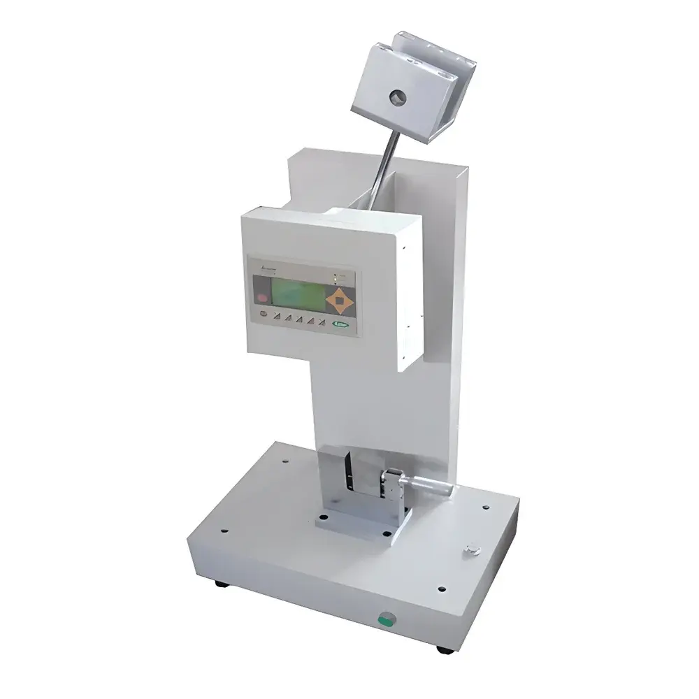
Jiubin Instruments JB/XJU-5.5B Digital Cantilever Beam Impact Tester
| Brand | Jiubin Instruments |
|---|---|
| Origin | Shanghai, China |
| Model | JB/XJU-5.5B |
| Impact Energy | 5.5 J |
| Impact Velocity | 3.5 m/s |
| Pendulum Radius (Impact Constant) | R = 0.8 ± 0.2 mm |
| Maximum Lifting Height | 95 mm |
| Standard Compliance | ISO 180, GB/T 1843, GB/T 1043, JB/T 8761 |
| Blade Angle | 30° ± 1° |
| Blade-to-Anvil Distance | 22 ± 0.2 mm |
| Energy Loss (Empty Swing) | ≤1% at 2.75 J |
Overview
The Jiubin Instruments JB/XJU-5.5B Digital Cantilever Beam Impact Tester is a precision-engineered mechanical testing system designed to determine the impact resistance and notch sensitivity of rigid non-metallic materials under standardized cantilever beam loading conditions. Operating on the principle of pendulum impact energy absorption, the instrument delivers controlled kinetic energy via a calibrated swinging pendulum that strikes a notched specimen clamped at one end—mimicking real-world stress concentration failure modes common in structural plastics and composite components. This method aligns with the fundamental mechanics described in ISO 180 and GB/T 1843, where absorbed energy per unit thickness (kJ/m²) is calculated from the difference between initial potential energy and residual swing energy after fracture. The device is optimized for laboratory environments requiring repeatable, traceable, and standards-compliant evaluation of brittle-to-tough transition behavior in thermoplastics, fiber-reinforced polymers, ceramics, and electrical insulating materials.
Key Features
- Digital microprocessor-controlled display with high-resolution energy readout (0.01 J resolution), eliminating parallax error associated with analog dials.
- Modular pendulum system supporting multiple nominal impact energies (0.6 J, 1 J, 2.75 J, and 5.5 J), enabling full-range characterization without hardware replacement.
- Precision-ground impact blade with certified geometry: 30° ± 1° included angle, R = 0.8 ± 0.2 mm tip radius, and strict tolerance (±0.2 mm) on blade-to-clamp distance (22 mm).
- Low-inertia pendulum design with verified energy loss performance: ≤0.5% at 5.5 J and ≤1% at 2.75 J during empty swings—ensuring measurement fidelity per JB/T 8761-1998 calibration requirements.
- Robust cast-iron base and hardened steel anvil assembly providing dimensional stability and vibration damping during high-speed impact events (3.5 m/s nominal strike velocity).
- Ergonomic specimen clamping mechanism with quick-release lever and micrometer-adjusted alignment guide to ensure consistent notch positioning across test series.
Sample Compatibility & Compliance
The JB/XJU-5.5B is validated for use with standardized rectangular bars (typically 80 × 10 × 4 mm) featuring a machined U- or V-notch per ISO 180 Type 1A or GB/T 1843 specifications. It accommodates rigid thermoplastics (e.g., ABS, PC, POM), thermosets (epoxy, phenolic), fiber-reinforced composites (glass/CFRP), technical ceramics, and electrically insulating laminates. All mechanical and metrological performance parameters comply with national and international regulatory frameworks—including GB/T 1043-2008 (Charpy-type verification), GB/T 1843-1996 (cantilever beam method), JB/T 8761-1998 (instrument validation protocol), and ISO 180:2019 (general test methodology). While not inherently GLP/GMP-certified, the system supports audit-ready documentation when integrated into quality management systems aligned with ISO/IEC 17025 requirements.
Software & Data Management
This standalone mechanical tester does not include embedded software or computer connectivity. All measurements are displayed locally on a high-contrast LED screen with manual data recording recommended for traceability. For laboratories requiring digital archiving, users may integrate external logging solutions using RS-232 or USB-to-serial adapters (third-party accessories). When deployed within regulated environments (e.g., ISO 9001-certified QC labs), operators should maintain logbooks documenting calibration dates, operator ID, environmental conditions (temperature/humidity), specimen lot numbers, and raw energy readings—supporting compliance with basic data integrity expectations under FDA 21 CFR Part 11 Annex 11 principles for non-automated systems.
Applications
- Quality control of injection-molded plastic housings in consumer electronics and automotive interiors.
- R&D screening of novel polymer blends and nanocomposites for aerospace-grade ductility enhancement.
- Batch release testing of electrical insulation components subjected to mechanical shock in switchgear assemblies.
- Evaluation of aging effects (UV, thermal, hydrolytic) on impact toughness retention in outdoor polymer applications.
- Academic research into fracture mechanics parameters (e.g., critical strain energy release rate GIC) through correlation with ASTM D5041-derived datasets.
- Supplier qualification audits requiring third-party verifiable impact performance against contractual material specifications.
FAQ
What standards does the JB/XJU-5.5B directly support?
It is fully compliant with GB/T 1843-1996, GB/T 1043-2008, ISO 180:2019, and JB/T 8761-1998 for cantilever beam impact testing of plastics.
Can this instrument be used for Charpy or Izod configurations?
No—it is specifically configured for cantilever beam (notched specimen clamped at one end, free-end impact), distinct from Izod (vertical clamp) or Charpy (horizontal three-point support) geometries.
Is calibration certification included with purchase?
Factory calibration is performed prior to shipment; however, users must establish periodic recalibration intervals per internal SOPs or ISO/IEC 17025 guidelines—typically annually or after 500 impacts, whichever occurs first.
What specimen dimensions are required?
Standard specimens measure 80 mm × 10 mm × 4 mm with a 2 mm deep, 0.8 mm radius notch located 22 mm from the clamped edge, as defined in GB/T 1843.
Does the system require compressed air or external power beyond standard AC input?
No—only single-phase 220 V AC, 50 Hz power supply is needed; no pneumatic or hydraulic auxiliary systems are involved.


")
