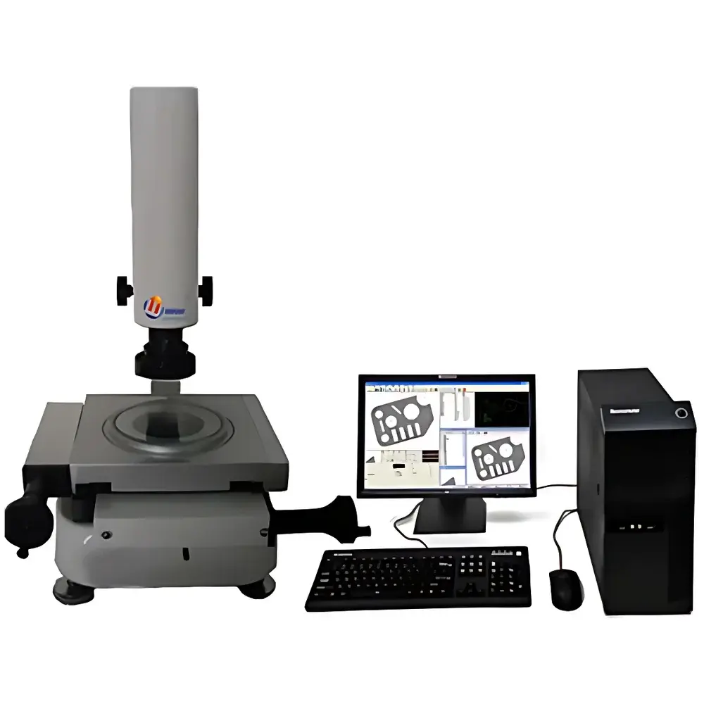
YANRUN YR1010 Image Measuring Instrument
| Brand | YANRUN |
|---|---|
| Origin | Shanghai, China |
| Manufacturer Type | Direct Manufacturer |
| Country of Origin | China |
| Model | YR1010 |
| Operation Mode | Manual |
| Measurement Accuracy | (3 + L/100) µm |
| Travel Range | X/Y/Z = 100 × 100 × 50 mm |
| Resolution | 0.001 mm |
| Optical Scale Accuracy | 0.001 mm |
| Repeatability | < ±0.003 mm |
| Zoom Lens Magnification | 15×–120× (total optical magnification) |
| Profile Light | Adjustable LED Bottom Light |
| Surface Light | Adjustable LED Top Light |
| Rotary Stage | 100 mm Diameter |
| Report Output | Excel (.xlsx), DXF (.dxf) |
Overview
The YANRUN YR1010 Image Measuring Instrument is a manually operated, high-resolution 2D geometric metrology system engineered for precision dimensional inspection of machined parts, stamped components, PCBs, and small mechanical assemblies in quality control and R&D environments. Based on digital optical imaging and coordinate metrology principles, the instrument captures high-contrast silhouette or surface images via dual-axis LED illumination (adjustable top surface light and bottom profile light), then performs sub-pixel edge detection and coordinate-based geometric computation. Its core architecture integrates a robust mechanical stage with backlash-free lead screws, high-stability granite base, and calibrated linear optical encoders—ensuring traceable measurement uncertainty consistent with ISO 10360-7 and VDI/VDE 2617 Part 6 standards for image-based measuring systems. Designed for laboratories and production floors where cost-effective, operator-guided metrology is required—without automation overhead—the YR1010 delivers certified accuracy of (3 + L/100) µm across its 100 mm × 100 mm working area, compliant with common QC requirements under ISO 9001 and IATF 16949 frameworks.
Key Features
- Manual XYZ stage with rapid coarse positioning and fine micrometer-driven movement; travel range: 100 mm (X) × 100 mm (Y) × 50 mm (Z)
- Backlash-free, zero-clearance lead screw transmission for stable, repeatable stage positioning
- High-resolution optical encoder system with 0.001 mm resolution and verified 0.001 mm scale accuracy
- Adjustable dual LED illumination: bottom-profile light for silhouette edge definition and top-surface light for feature contrast enhancement
- 100 mm diameter precision rotary stage for angular alignment and multi-view inspection of rotational parts
- 15×–120× total optical magnification via zoom lens assembly, enabling scalable feature interrogation without mechanical refocusing
- Integrated real-time image capture and on-screen measurement interface with crosshair auto-edge detection algorithm
Sample Compatibility & Compliance
The YR1010 accommodates flat, low-relief, and rotationally symmetric parts up to 100 mm in diameter and 50 mm in height. Typical applications include metal stampings, plastic injection-molded housings, ceramic substrates, gaskets, and precision sheet-metal components. Sample mounting is facilitated by standard kinematic clamps and vacuum chucks (optional). The system supports compliance workflows per ISO 8015 (geometrical product specifications), ISO 1101 (geometric tolerancing), and ASME Y14.5–2018. Measurement data—including raw coordinates, tolerance evaluation results, and annotated images—can be exported with full audit trail metadata, supporting GLP/GMP documentation practices where electronic records are retained per ALCOA+ principles. While not FDA 21 CFR Part 11–validated out-of-the-box, the software architecture permits integration with validated document management systems via standardized file exports (DXF, XLSX).
Software & Data Management
The proprietary YR-Measure software provides full 2D geometric metrology functionality including point, line, circle, arc, distance, angle, polar coordinate conversion, pitch, and incremental offset calculations. It implements ISO 5459–compliant datum establishment and GD&T evaluation (position, concentricity, parallelism, perpendicularity, etc.), with graphical deviation mapping overlaid directly on measured features. All measurements are stored with timestamp, operator ID, and calibration status flags. Image files (BMP/PNG) and coordinate datasets are saved in native project format; reports export to Excel (.xlsx) with customizable templates and CAD-ready DXF files for downstream design validation. Data transfer is supported via local network, USB, or email—enabling remote review without proprietary viewer dependencies.
Applications
- First-article inspection of CNC-machined components against engineering drawings
- Dimensional verification of injection-molded plastic parts for shrinkage and warpage analysis
- PCB land pattern and solder paste deposit geometry assessment
- Tooling and fixture wear monitoring via periodic re-measurement of reference features
- Educational use in metrology labs for teaching coordinate measurement fundamentals and GD&T interpretation
- Supplier quality audits requiring portable, non-contact 2D verification capability
FAQ
What is the maximum part height the YR1010 can accommodate?
The Z-axis travel is 50 mm, allowing measurement of parts up to approximately 45 mm in height when mounted on the standard stage—accounting for objective working distance and lighting clearance.
Does the system support automatic edge detection?
Yes. The software includes sub-pixel auto-edge detection triggered by crosshair placement, reducing operator-induced variability in manual edge selection.
Can measurement results be integrated into a company’s MES or QMS?
While the YR1010 does not feature native API or database connectivity, all output files (Excel, DXF, PNG) conform to open, non-proprietary formats compatible with third-party data ingestion pipelines.
Is calibration certification included with purchase?
A factory calibration report traceable to national standards (via CNAS-accredited lab) is provided; annual recalibration is recommended per ISO/IEC 17025 guidelines.
What maintenance is required for long-term accuracy stability?
Routine cleaning of optical surfaces and stage guides, periodic verification using certified gauge blocks and ring gauges, and biannual encoder calibration check are advised.