Aolong Industrial Micro-CT Inspection Service
| Brand | Aolong |
|---|---|
| Origin | Liaoning, China |
| Manufacturer Type | OEM Manufacturer |
| Region of Origin | Domestic (China) |
| Model | Aolong |
| Pricing | Upon Request |
Overview
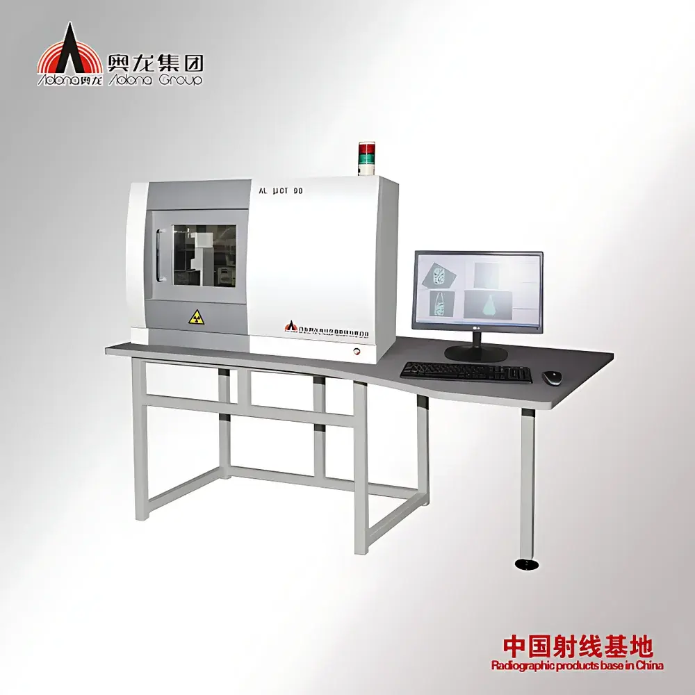
Aolong Industrial Micro-CT Inspection Service leverages high-resolution X-ray computed tomography to deliver non-destructive, volumetric 3D imaging of internal and external structures. Based on the physical principle of differential X-ray attenuation through materials of varying density and atomic composition, this service reconstructs isotropic voxel datasets with micron-level spatial resolution—enabling quantitative analysis without sample sectioning or physical intervention. Deployed across R&D laboratories, quality assurance departments, and failure analysis centers, it serves as a metrological-grade solution for dimensional validation, defect characterization, material distribution mapping, and reverse engineering in regulated and research-intensive environments.
Key Features
- Non-invasive 3D volumetric scanning with sub-micron geometric resolution (system-dependent), supporting full-field internal feature capture—including hidden geometries, undercuts, and enclosed voids.
- Quantitative defect analysis: automated segmentation and color-coded visualization of porosity, inclusions, shrinkage cavities, and delaminations; statistical reporting of defect volume fraction, size distribution (histogram output), and spatial coordinates.
- Precision dimensional metrology: traceable measurement of distances, radii, angles, wall thicknesses, and GD&T parameters directly from reconstructed CT volumes—compliant with ISO 15530-3 and VDI/VDE 2630 guidelines for CT-based measurement.
- CT-CAD comparison module: deviation mapping against nominal CAD models with true-color error heatmaps, enabling comprehensive first-article inspection and production part approval process (PPAP) support.
- Multi-material contrast differentiation: capable of resolving low-contrast interfaces in composites, ceramics, sintered metals, geological specimens, and biological tissues—facilitating phase segmentation and density gradient analysis.
- Assembly integrity verification: detection and 3D localization of solder joint voids, wire bond lift-offs, encapsulation delamination, and micro-cracks in electronic packages and MEMS devices—without disassembly or destructive cross-sectioning.
Sample Compatibility & Compliance
The service accommodates samples ranging from small electronic components (<5 mm) to large industrial castings (up to Ø400 mm × H500 mm), including but not limited to aluminum die-castings, turbine blades, composite brake rotors, ceramic insulators, pharmaceutical blister packs, fossilized specimens, and geological core samples. All scanning protocols adhere to ASTM E1441 (Standard Guide for Computed Tomography), ISO/IEC 17025:2017 (general competence requirements for testing laboratories), and support GLP/GMP documentation workflows. Raw projection data and reconstructed volumes are archived with metadata compliant with DICOM-CT standards for long-term traceability.
Software & Data Management
Inspection reports are generated using industry-standard reconstruction and analysis software (e.g., VGStudio MAX, phoenix datos|x, or custom Aolong-developed modules), supporting full audit trails, user access controls, and versioned dataset management. Measurement results include uncertainty estimation per ISO/IEC GUIDE 98-3 (GUM). Export formats include STL, PLY, OBJ, CSV (defect statistics), and annotated PDF reports with embedded 3D viewers. Data handling complies with ISO 27001-aligned information security practices; raw projections and reconstructions are retained for minimum 10 years upon client request.
Applications
- Automotive & Aerospace: Porosity analysis in high-pressure die-cast engine blocks; dimensional verification of turbine airfoils; assembly validation of fuel injectors and sensor housings.
- Electronics & Semiconductors: Solder joint integrity assessment in BGA packages; void detection in underfill materials; 3D metrology of stacked-die ICs.
- Materials Science: Quantification of pore network topology in metal foams and battery electrodes; crack propagation tracking in thermal barrier coatings; fiber orientation mapping in CFRP laminates.
- Geoscience & Paleontology: Digital fossil extraction and morphometric analysis; porosity-permeability correlation in reservoir rock cores; mineral phase distribution in ore samples.
- Medical Device & Pharma: Seal integrity evaluation of sterile barrier systems; coating thickness uniformity in inhaler canisters; tablet internal structure and excipient distribution analysis.
- Reverse Engineering & Additive Manufacturing: CT-based digitization of legacy parts for CAD model regeneration; as-built vs. as-designed validation of LPBF and binder-jetted components.
FAQ
What is the typical turnaround time for a standard CT inspection report?
Standard reporting for parts ≤150 mm in diameter is completed within 5–7 business days after sample receipt, inclusive of reconstruction, analysis, and technical review. Expedited service (≤72 hours) is available upon prior agreement.
Can CT data be used for regulatory submissions (e.g., FDA, FAA)?
Yes—datasets are generated under documented SOPs; full traceability (source projections, reconstruction parameters, calibration records) is provided. Reports may be structured to align with FDA 21 CFR Part 11 requirements when electronic signatures and audit trails are implemented.
Is there a minimum sample quantity requirement?
No minimum quantity applies; single-part inspections are routinely performed. Batch scanning with statistical sampling plans (e.g., AQL-based) is supported for production lot verification.
Do you provide raw projection data and reconstruction parameters?
Yes—clients receive raw sinograms, reconstructed 32-bit TIFF stacks, and complete metadata logs (kV/mA/focal spot size/filter/detector binning/reconstruction algorithm/version) as standard deliverables.
How is measurement uncertainty quantified in CT-based metrology?
Uncertainty budgets follow ISO/IEC GUIDE 98-3 and VDI/VDE 2630 Part 1.1, incorporating contributions from beam hardening, motion artifacts, noise, voxel size, surface extraction method, and reference standard calibration—reported per critical dimension in final deliverables.


