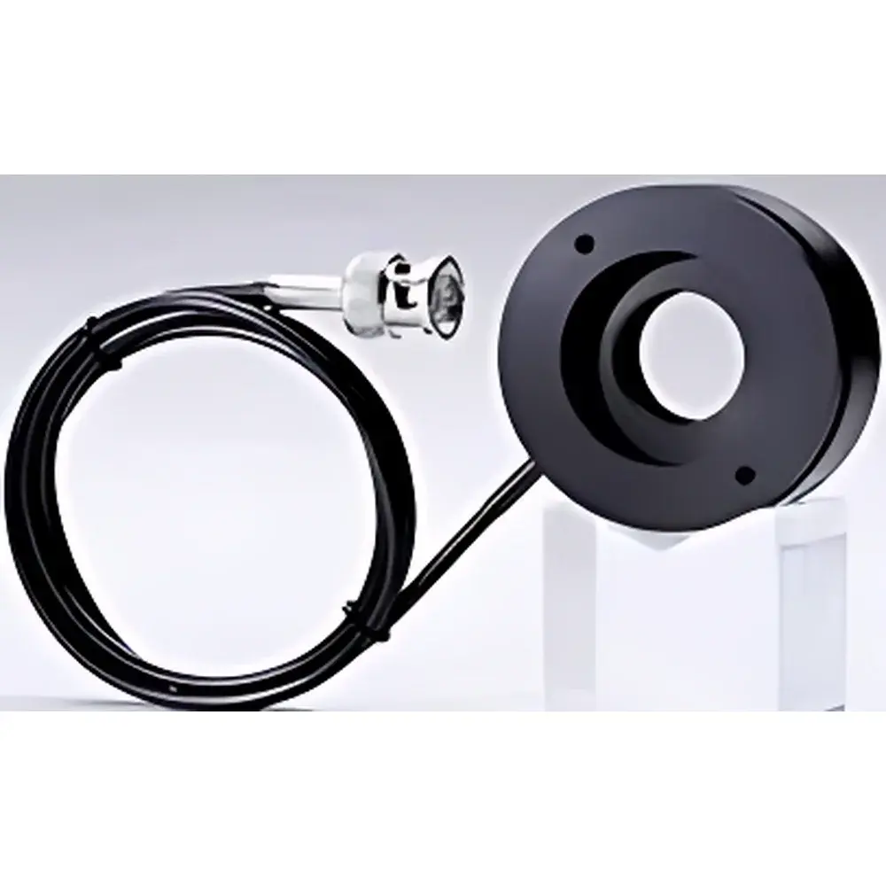
Jenoptik PLM Series Liquid Crystal Phase Modulator
| Brand | Jenoptik |
|---|---|
| Origin | USA |
| Manufacturer Type | Authorized Distributor |
| Origin Category | Imported |
| Model | PLM Series Liquid Crystal Phase Modulator |
| Component Category | Optical Modulator (Not Light Source) |
| Key Optical Function | Voltage-Controlled Birefringence-Based Phase Delay Tuning |
Overview
The Jenoptik PLM Series Liquid Crystal Phase Modulator is a high-stability, solid-state optical component engineered for precise, non-mechanical phase retardation control in coherent optical systems. Unlike piezoelectric or motorized waveplate-based modulators, the PLM leverages the electro-optic birefringence modulation of nematic liquid crystal (LC) layers under applied DC or low-frequency AC voltage. Its operational principle relies on the reorientation of LC molecules in response to an electric field, thereby dynamically altering the effective refractive index experienced by orthogonal polarization components (ordinary and extraordinary rays). This enables continuous, analog phase shift tuning across a defined spectral range—typically spanning visible to near-infrared wavelengths (e.g., 400–1100 nm)—with sub-wavelength resolution and high repeatability. Designed for integration into interferometric setups, adaptive optics testbeds, quantum optics experiments, and polarization-encoded communication systems, the PLM delivers robust performance without moving parts, minimizing mechanical drift, vibration sensitivity, and long-term wear.
Key Features
- Voltage-driven phase modulation: Continuous, analog control of optical path difference (OPD) via applied bias (typically 0–10 V DC or low-frequency AC); no mechanical actuation required.
- High extinction ratio (>500:1) and low insertion loss (<1.5 dB typical) across standard telecom and visible bands.
- Fast response time: Rise/fall times <20 ms (full 0–2π retardation), suitable for quasi-static and low-bandwidth dynamic applications.
- Thermally stabilized LC cell architecture with integrated temperature compensation circuitry for improved phase stability over ±2°C ambient variation.
- Standard AR-coated fused silica substrates (optional custom coatings available per wavelength band).
- Modular mounting interface compatible with standard 25 mm or 50 mm optical rail systems and kinematic mounts.
Sample Compatibility & Compliance
The PLM is optimized for use with linearly polarized input beams aligned to its designated fast/slow axis orientation. It supports collimated beams up to its specified clear aperture (standard options: Ø10 mm, Ø15 mm, Ø25 mm). Device operation complies with IEC 61000-6-3 (EMC emission limits) and RoHS 2011/65/EU directives. While not classified as a medical or safety-critical device, its design adheres to ISO 10110-7 surface quality standards (scratch-dig 20-10) and meets typical laboratory-grade environmental specifications per MIL-STD-810G for shock/vibration resistance during handling and transport. Calibration reports traceable to NIST-traceable polarimetric standards are available upon request for metrology-grade deployments.
Software & Data Management
The PLM operates as a standalone analog device but integrates seamlessly with common lab control environments. Analog voltage input is compatible with standard DAQ systems (e.g., National Instruments USB-6211, Thorlabs KDC101) and programmable power supplies (e.g., Keysight B2900 series). Optional digital interface modules support USB or RS-232 communication for firmware-upgradable control logic and real-time voltage-phase lookup table (LUT) loading. All supplied drivers and configuration utilities conform to IEEE 1278.1–2020 interoperability guidelines and support audit-trail logging for GLP-compliant experimental records. No proprietary runtime or OS-specific software is required; control scripts are readily implementable in Python (PyVISA), MATLAB, or LabVIEW.
Applications
- Adaptive optics calibration: Generating controlled Zernike mode aberrations for wavefront sensor validation.
- Quantum optics: Path-length stabilization in Mach–Zehnder and Sagnac interferometers for single-photon interference experiments.
- Polarization state generation: Synthesizing arbitrary Stokes vectors via sequential or cascaded PLM configurations.
- Optical coherence tomography (OCT): Reference arm phase scanning for dispersion compensation and phase-resolved imaging.
- Laser cavity mode control: Intracavity phase tuning for frequency locking and linewidth narrowing in external cavity diode lasers (ECDLs).
- Teaching laboratories: Demonstrating electro-optic effects, Poincaré sphere navigation, and Jones matrix formalism in undergraduate photonics courses.
FAQ
What is the maximum achievable phase retardation range?
The PLM achieves up to 2π (360°) optical phase delay at its design wavelength, with linearity better than ±3% over 0–1.8π under calibrated voltage drive.
Is the device sensitive to temperature fluctuations?
Yes—phase retardation exhibits a temperature coefficient of ~0.02 rad/°C near 25°C; thermal stabilization is recommended for applications requiring sub-0.1λ stability over extended periods.
Can multiple PLMs be cascaded for higher-order polarization control?
Yes—cascaded configurations (e.g., two PLMs with orthogonal alignment) enable full Poincaré sphere coverage and independent control of retardance and azimuthal orientation.
Does the PLM require driver electronics?
A stable, low-noise voltage source (±0.1% regulation, <100 µV RMS ripple) is mandatory; dedicated driver boards with built-in temperature monitoring and LUT-based compensation are available as optional accessories.
Is laser-induced damage threshold (LIDT) specified?
LIDT is tested per ISO 21254-1:2011; typical values are 1.5 J/cm² for 10 ns pulses at 1064 nm and >500 W/cm² CW at 532 nm—exact values depend on aperture size and coating selection.


