Radiant Zemax SIG-400 Imaging Goniophotometer
| Brand | Radiant Zemax |
|---|---|
| Origin | USA |
| Manufacturer Type | Authorized Distributor |
| Origin Category | Imported |
| Model | SIG-400 |
| Pricing | Upon Request |
Overview
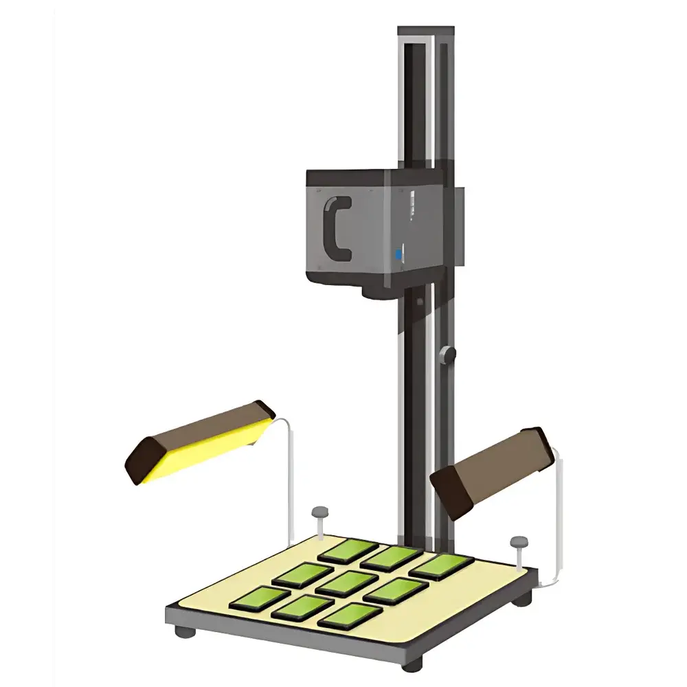
The Radiant Zemax SIG-400 Imaging Goniophotometer is a high-precision, motorized imaging-based angular measurement system engineered for the quantitative characterization of near-field photometric and colorimetric distributions from LEDs, micro-LEDs, OLEDs, and other small-area light sources. Unlike traditional point-sensor goniometers, the SIG-400 employs a calibrated, thermoelectrically cooled scientific CCD imager coupled with a precision multi-axis goniometric stage to capture spatially resolved luminance (cd/m²), chromaticity (CIE x,y; u′,v′), correlated color temperature (CCT), and ΔE across the full emission hemisphere — all in a single, synchronized acquisition sequence. Its core architecture integrates mechanical run-out compensation (<15 µm centering accuracy), optical alignment stability (≤0.015 mm mechanical-optical-software run-out), and CIE 1931-compliant XYZ tristimulus filtering to ensure traceable, repeatable measurements aligned with ISO/CIE photometric standards. Designed for R&D labs, LED packaging facilities, and optical design teams, the SIG-400 delivers the foundational near-field data required for accurate ray-set generation, Radiant Source Model (RSM) creation, and predictive optical simulation in tools such as LightTools, TracePro, and Zemax OpticStudio.
Key Features
- Precision goniometric stage with ±10° to +370° polar rotation and ±37° azimuthal travel relative to lamp axis, enabling full hemispherical coverage with <0.10°/min angular resolution
- Thermoelectrically cooled, full-frame scientific CCD sensor offering 16-bit dynamic range (65,536:1) and selectable resolutions: 512 × 512 or 1024 × 1024 pixels
- Modular field-of-view (FOV) optics: standard (2–50 mm / 5–125 mm), micro (0.6 mm / 1.3 mm), and macro (90 mm / 225 mm) configurations optimized for die-level, package-level, and array-level measurements
- CIE 1931 XYZ color filter set with factory-calibrated neutral density filters (ND0–ND2 standard; ND3–ND5 optional) for high-dynamic-range luminance and chromaticity mapping
- Integrated real-time image acquisition, auto-centering, and geometric distortion correction algorithms ensuring sub-pixel registration accuracy and repeatability ≤0.5% (k=2)
- Structural steel-cast monocoque frame with passive thermal management, minimizing thermal drift during extended measurement sequences
Sample Compatibility & Compliance
The SIG-400 accommodates bare LED dies (≥100 µm), surface-mount packages (e.g., 0402 to 3535), COB modules, and miniature display pixels. Sample mounting uses vacuum chuck or kinematic fixture interfaces compatible with industry-standard probe stations. All photometric and colorimetric outputs comply with CIE S 025/E:2015, IES LM-79-19, and ISO/CIE 11664-1:2019. Measurement uncertainty budgets are documented per ISO/IEC 17025:2017 requirements and support GLP/GMP audit readiness. Software-generated reports include full metadata traceability (exposure time, ND filter position, calibration timestamp, lens ID, temperature log), satisfying FDA 21 CFR Part 11 electronic record integrity requirements when deployed with validated SIG 2.0 software configuration.
Software & Data Management
SIG 2.0 software provides end-to-end control, analysis, and export functionality. It supports automated goniometric scan sequencing, real-time luminance/chromacity preview, and on-the-fly histogram normalization. Key outputs include: luminance cross-sections, candela polar plots, 3D luminance surface maps, iso-luminance contours, and CIE u′v′ chromaticity distribution overlays. All raw images and processed datasets are stored in vendor-neutral TIFF/HDF5 formats with embedded EXIF metadata. The software enables direct export of RSM-compatible .rad files (including spectral and spatial data), CSV tables for statistical process control (SPC), and PDF reports with configurable templates. Audit trail logging records every user action, parameter change, and calibration event with timestamps and operator IDs.
Applications
- Generation of near-field luminance and chromaticity distributions for optical modeling and ray-tracing simulations
- Validation of LED package optical performance against design specifications (e.g., beam shape, color uniformity, CCT shift vs. angle)
- Quality control of wafer-level and packaged LED production batches using automated pass/fail thresholds on luminance uniformity (ΔL/L), chromaticity deviation (Δu′v′), and angular CCT consistency
- Characterization of micro-LED arrays for AR/VR displays, including pixel-level non-uniformity mapping and viewing-angle-dependent color shift analysis
- Support for DOE verification, lens/housing optimization, and thermal-optical coupling studies under controlled environmental conditions
FAQ
What types of light sources can the SIG-400 measure?
The SIG-400 is optimized for small-area emitters including bare LED dies, SMD packages (0402 to 3535), COBs, mini-LEDs, micro-LEDs, and OLED pixels — typically up to 25 mm in maximum dimension.
Does the system support spectral measurement?
No — the SIG-400 performs tristimulus colorimetry using CIE 1931 XYZ filters. For spectral radiance, Radiant recommends pairing with its TT-GBA spectroradiometer or integrating external spectrometers via trigger synchronization.
How is calibration maintained across different FOV lenses and ND filters?
Each lens/ND combination is individually characterized during factory calibration. SIG 2.0 automatically applies the corresponding spatial and radiometric correction matrix based on active hardware configuration.
Can the SIG-400 be integrated into an automated production test line?
Yes — it supports Ethernet/IP and TCP/IP communication protocols, programmable API (C++/Python), and hardware trigger I/O for synchronization with pick-and-place handlers and environmental chambers.
What is the typical measurement time for a full hemispherical scan?
Scan duration depends on resolution, exposure, and angular step size; a standard 1°-step hemispherical acquisition at 1024×1024 resolution takes approximately 8–12 minutes, including auto-focus and centering routines.