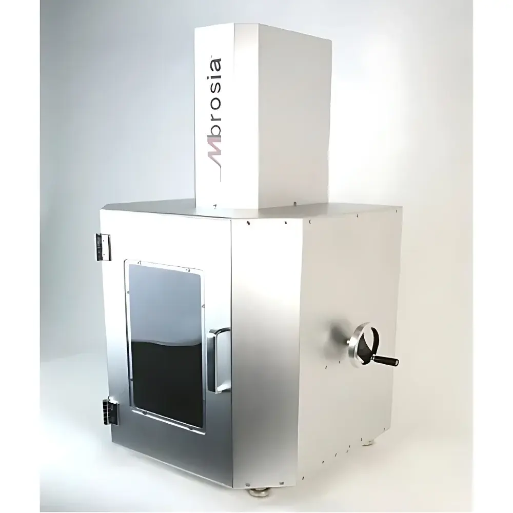
UFT High-Temperature Ultrasonic (Ultra-High-Frequency) Fatigue Testing Machine
| Origin | South Korea |
|---|---|
| Manufacturer Type | Authorized Distributor |
| Origin Category | Imported |
| Model | UFT |
| Price Range | USD 140,000 – 280,000 |
| Instrument Type | Ultra-High-Frequency Fatigue Tester |
| Maximum Test Load | Up to 1000 MPa Stress Amplitude |
| Frequency Range | 20 kHz ± 500 Hz |
| Unit Weight | 500 kg |
Overview
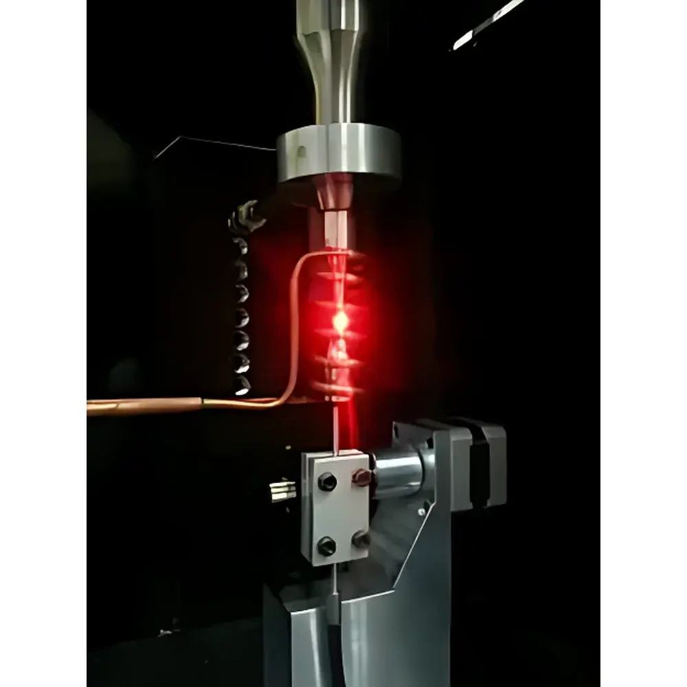
The UFT High-Temperature Ultrasonic Fatigue Testing Machine is an advanced resonant-mode fatigue system engineered for ultra-high-cycle fatigue (UHCF) evaluation of metallic structural materials under controlled thermal and mechanical conditions. Operating on the principle of longitudinal ultrasonic resonance at 20 kHz, the system utilizes piezoelectric transducers to generate high-frequency harmonic vibrations, which are mechanically amplified via titanium-based horn assemblies to deliver precise, high-stress cyclic loading directly to the specimen. Unlike conventional servo-hydraulic or electromagnetic fatigue testers—limited to frequencies below 500 Hz—the UFT achieves test durations orders of magnitude shorter: a 1010-cycle test at 100 Hz would require ~3.2 years; the same cycle count at 20 kHz completes in approximately 6 days. This capability enables reliable characterization of fatigue behavior in the critical 105–1011 cycle regime—where traditional methods fail due to time constraints and thermal drift—and supports fundamental research into crack initiation from microstructural defects (e.g., inclusions, grain boundaries) under high-frequency, low-thermal-dissipation conditions.
Key Features
- Resonant ultrasonic actuation with piezoelectric stack transducer (20 kHz ± 500 Hz), delivering stable, high-fidelity sinusoidal stress waveforms
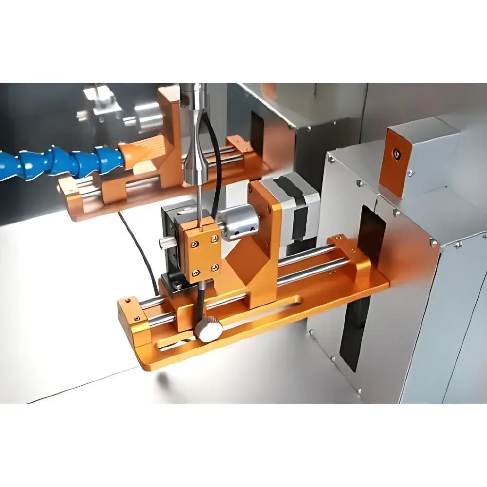
- Titanium booster and horn assembly tuned to 20 kHz ± 30 Hz resonance, optimized for minimal internal damping and thermal generation
- Adjustable displacement amplitude range: ±10 µm to ±70 µm, calibrated and monitored in real time via fiber-optic displacement sensors
- Integrated stepper-motor-driven sensor positioning system for precise alignment and repeatability across specimen geometries
- Air-cooled thermal management architecture—no hydraulic oil, water cooling, or external chillers required
- High-efficiency power consumption: typical operational load ≤2 kW (vs. >200 kW for equivalent hydraulic systems)
- Modular high-temperature extension option: induction-heated furnace (up to 1000 °C), compliant with ASTM E209 and ISO 12106 for elevated-temperature fatigue testing
Sample Compatibility & Compliance
The UFT is validated for use with metals exhibiting strong acoustic impedance matching and low viscoelastic loss at 20 kHz—including high-strength steels (e.g., maraging steel, bearing steel), Ti-6Al-4V, 7075 aluminum, and other aerospace-grade alloys. Specimens must be designed as resonant bars (typically dog-bone or hourglass geometry) with nodal points aligned to fixture interfaces. Materials unsuitable for testing include polymers, ceramics, and highly damped alloys (e.g., some Mg or Zn alloys), which either fail to sustain resonance or undergo excessive hysteretic heating (>10 °C rise per 106 cycles). All mechanical and thermal configurations comply with ISO 1099 (metallic materials—fatigue testing—axial force-controlled method), ASTM E466 (standard practice for conducting force-controlled constant amplitude axial fatigue tests), and support GLP-compliant audit trails when paired with optional FDA 21 CFR Part 11–enabled software modules.
Software & Data Management
The UFT control suite provides full PC-based configuration, real-time monitoring, and automated data logging. Key functionalities include automatic resonance frequency tracking and compensation, dynamic stress calibration using integrated load cell feedback (optional), and closed-loop amplitude regulation. Test parameters—including cycle count, peak stress, temperature ramp rate, and mean stress offset (via optional bias loading module)—are programmable via intuitive GUI. Raw sensor outputs (displacement, voltage, temperature) are timestamped and saved in dual formats: native binary for post-processing and export-ready CSV/Excel files. Stress–life (S–N) curves, hysteresis loops, and resonance drift trends are generated automatically. Audit logs record operator ID, parameter changes, and system status—essential for ISO/IEC 17025-accredited laboratories.
Applications
- UHCF life prediction of turbine blades, landing gear components, and fasteners in aerospace and power generation
- Fundamental studies of fatigue crack initiation mechanisms at inclusion clusters or grain boundaries under high-frequency loading
- Thermo-mechanical fatigue assessment of coated superalloys at 600–1000 °C using synchronized induction heating
- Dynamic elastic modulus evolution monitoring (per ASTM E1876) during fatigue cycling
- Validation of physics-based fatigue models (e.g., Kitagawa–Takahashi diagram, FKM nonlinear approach) under extreme cycle counts
- Qualification testing per OEM specifications (e.g., Rolls-Royce RRP 7872, GE Aerospace PSS-100)
FAQ
What is the maximum achievable stress amplitude at 20 kHz?
The system delivers up to 1000 MPa nominal stress amplitude in tension–compression mode, contingent upon specimen geometry, material acoustic properties, and resonant tuning accuracy.
Can the UFT perform tests with non-zero mean stress (R-ratio control)?
Yes—when equipped with the optional static bias loading module, the system supports controlled mean stress application, enabling R-ratio testing from –1 (fully reversed) to +0.8.
Is the high-temperature module compatible with vacuum or inert gas environments?
The standard induction heating system operates in ambient air; however, custom vacuum chamber integration (≤10−3 mbar) and argon-purged enclosures are available as engineering options.
How is calibration traceability maintained?
Displacement sensors are factory-calibrated against NIST-traceable laser interferometry; force calibration follows ISO 376 procedures using certified reference load cells.
What maintenance intervals are recommended for long-term reliability?
Piezoelectric stacks require no routine replacement; annual verification of horn resonance frequency, amplifier gain linearity, and thermal sensor drift is advised per ISO/IEC 17025 preventive maintenance protocols.


