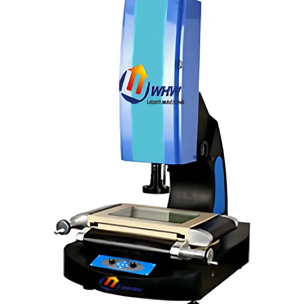
YANRUN YR-D4030 Non-Contact Vision Measuring Machine
| Brand | YANRUN |
|---|---|
| Origin | Shanghai, China |
| Manufacturer Type | Direct Manufacturer |
| Model | YR-D4030 |
| Table Top Dimensions (Metal) | 458 × 558 mm |
| Glass Stage Dimensions | 450 × 350 mm |
| Motion Travel (X×Y) | 400 × 300 mm |
| Overall Dimensions | 1080 × 770 × 1110 mm |
| Load Capacity | ≥450 kg |
| Base Platform Size | 1120 × 730 × 780 mm |
| Drive Mechanism | X/Y-axis — Precision Linear Rod Guides |
| Z-axis Vertical Travel | 250 mm |
| Digital Readout Resolution (X/Y/Z) | 0.0005 mm |
| Positioning Accuracy (X/Y) | ≤(3 + L/200) μm |
| Imaging System | High-Resolution Color CCD Camera |
| 0.7–4.5× Zoom Lens (Total Video Magnification | 30–230× |
| Illumination | Quadrant-Independent Adjustable LED Lighting |
| Power Supply | AC 220 V ±10%, 50 Hz |
| Operating Environment | 20 °C ±3 °C, 45–75% RH |
Overview
The YANRUN YR-D4030 Non-Contact Vision Measuring Machine is an optomechanical metrology system engineered for high-precision, two-dimensional and three-dimensional geometric inspection of machined parts, sheet metal components, PCBs, molds, and precision stampings. It operates on the principle of digital image acquisition and sub-pixel edge detection, utilizing calibrated optical magnification and coordinate transformation algorithms to determine dimensional features without physical probe contact. The system integrates a rigid granite-based mechanical structure, motorized Z-axis elevation, and a thermally stable optical path—designed to meet the repeatability and traceability requirements of ISO 10360-7 (coordinate measuring machines) and ASTM E2925 (standard practice for evaluating vision measurement systems). Its non-destructive nature makes it especially suitable for soft-surface materials, thin-walled components, and finished parts where tactile probing risks deformation or surface marking.
Key Features
- Rigid mechanical architecture with reinforced base platform (1120 × 730 × 780 mm) supporting ≥450 kg load capacity—minimizing vibration-induced measurement drift during extended operation.
- High-stability motion system: X- and Y-axes employ precision-ground linear rod guides for low-friction, backlash-free translation; Z-axis utilizes a preloaded ball screw mechanism enabling smooth, repeatable vertical positioning over 250 mm travel.
- Sub-micron resolution metrology chain: 0.0005 mm digital encoder resolution across all axes, coupled with certified geometric error compensation—achieving stated X/Y coordinate uncertainty of ≤(3 + L/200) μm per ISO 10360-2.
- Modular optical imaging subsystem: Industry-standard color CCD sensor paired with a continuously variable 0.7–4.5× zoom lens, delivering total video magnifications from 30× to 230× (extendable to 440× with optional 2× auxiliary objective), ensuring adaptability across feature sizes from 0.02 mm to >50 mm.
- Four-quadrant independent LED illumination control enables dynamic contrast optimization for diverse surface finishes—including matte, reflective, translucent, or textured geometries—without manual repositioning or external lighting fixtures.
Sample Compatibility & Compliance
The YR-D4030 accommodates workpieces up to 400 mm × 300 mm in planar footprint and 250 mm in height, supported directly on either the 450 × 350 mm optical glass stage or the 458 × 558 mm precision-machined metal table. Its non-contact methodology ensures compatibility with fragile, coated, or heat-sensitive samples—including polymer films, semiconductor wafers, injection-molded housings, and precision gears. The system conforms to environmental operating specifications aligned with ISO 22476-1 (geotechnical testing) and VDI/VDE 2617 Part 9 (optical measuring instruments), requiring ambient temperature stability of ±3 °C around 20 °C and relative humidity between 45–75% to maintain calibration integrity. All mechanical and optical components are manufactured and assembled in Shanghai under ISO 9001-certified production controls.
Software & Data Management
The instrument is supplied with proprietary YANRUN Vision Metrology Software (v5.x), compliant with GLP/GMP documentation standards. It supports full audit trail logging—including operator ID, timestamp, measurement parameters, image capture, and calibration history—in accordance with FDA 21 CFR Part 11 requirements for electronic records and signatures. Measurement reports are exportable in PDF, CSV, and XML formats, with embedded GD&T annotations (e.g., position, concentricity, profile) per ASME Y14.5 and ISO 1101. Software includes automated edge detection algorithms, multi-point best-fit circle/line regression, and batch report generation for statistical process control (SPC) integration. Optional API access enables direct linkage to MES or QMS platforms via TCP/IP or OPC UA protocols.
Applications
- Dimensional verification of CNC-machined aerospace components (e.g., turbine blade root profiles, flange hole patterns).
- PCB solder mask alignment and pad geometry validation prior to SMT assembly.
- Tooling inspection for injection molds—including cavity depth, gate diameter, and ejection pin location.
- Automotive brake caliper bracket flatness and bolt-hole positional tolerance analysis.
- Medical device component metrology—such as catheter hub symmetry, syringe barrel wall thickness uniformity, and implant surface feature mapping.
FAQ
What is the maximum part height that can be measured with the Z-axis travel?
The Z-axis provides 250 mm of vertical clearance above the glass stage, permitting measurement of parts up to 250 mm tall when placed directly on the stage surface.
Does the system support automated measurement routines for high-volume production environments?
Yes—programmable measurement sequences, part recognition via template matching, and pass/fail decision logic are fully supported within the standard software suite.
Is NIST-traceable calibration documentation included with delivery?
Each unit ships with a factory calibration certificate referencing NIST-traceable standards for length, angle, and magnification; on-site recalibration services are available through authorized YANRUN service centers.
Can third-party CAD models be imported for nominal-to-actual comparison?
Yes—the software accepts STEP, IGES, and DXF files for overlay-based deviation analysis, including color-coded residual error mapping.
What maintenance intervals are recommended for long-term accuracy retention?
Annual verification of axis linearity, optical magnification calibration, and illumination uniformity is advised; daily cleaning of optical surfaces and monthly encoder zero-checking are sufficient for routine operation.