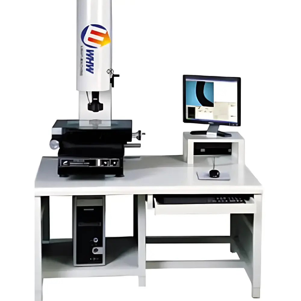
YANRUN YR-F4030 Practical Image Measuring System
| Brand | YANRUN |
|---|---|
| Origin | Shanghai, China |
| Manufacturer Type | Direct Manufacturer |
| Model | YR-F4030 |
| Table Load Capacity | ≥450 kg |
| X-Y Travel Range | 400 mm × 300 mm |
| Z-Axis Vertical Travel | 175 mm |
| Positional Accuracy | ≤(3 + L/200) µm |
| Digital Readout Resolution (X/Y/Z) | 0.0005 mm |
| Optical Magnification | 28×–180× |
| Objective Lens | Dual-focus zoom lens (0.7×–4.5×) |
| Camera | SONY color CCD |
| Illumination | Adjustable LED surface & transmitted lighting |
| Power Supply | 220 V ±10%, 50 Hz |
| Operating Environment | 20 °C ±3 °C, 45–75% RH |
| Software | Standard automatic edge-detection metrology suite with deburring, alignment, and geometric feature extraction (line, circle, distance, angle, parallelism, perpendicularity) |
Overview
The YANRUN YR-F4030 Practical Image Measuring System is a high-stability, manually operated coordinate measuring instrument engineered for non-contact two-dimensional geometric metrology in quality control laboratories, precision machining workshops, and R&D facilities. It operates on the principle of optical projection and digital image analysis: a high-resolution SONY color CCD camera captures magnified images of parts placed on a precision-ground granite or composite base, while dual-path LED illumination—comprising both coaxial surface and bottom-transmitted light—enables robust contrast for edge detection across diverse material surfaces (e.g., metal, plastic, ceramic, PCBs). The system employs a fixed-stage design with motor-assisted manual motion control along X- and Y-axes (400 mm × 300 mm travel), and a manually adjustable Z-axis (175 mm lift range) to accommodate varying part heights. Measurement data are processed in real time using calibrated pixel-to-micron mapping algorithms, traceable to NIST-traceable standards via documented calibration procedures.
Key Features
- Robust mechanical architecture with ≥450 kg load capacity support table (1250 mm × 900 mm × 780 mm), ensuring vibration damping and long-term stability under workshop conditions.
- Dual-path illumination system: independently adjustable LED ring light for surface feature contrast and uniform transmitted backlight for silhouette-based contour measurement.
- High-fidelity optical train featuring a dual-magnification zoom objective (0.7×–4.5×), delivering total system magnifications from 28× to 180×—optimized for both macro-feature overview and micron-level edge resolution.
- Sub-micron positional repeatability supported by 0.5 µm digital readout resolution (X/Y/Z) and linear scale feedback; certified positional accuracy per ISO 10360-2: ≤(3 + L/200) µm.
- Integrated metrology software with automated edge detection, noise filtering, and sub-pixel interpolation—capable of measuring lines, circles, arcs, distances, angles, concentricity, parallelism, and perpendicularity without manual cursor placement.
Sample Compatibility & Compliance
The YR-F4030 accommodates parts up to 400 mm × 300 mm in footprint and 175 mm in height, including machined housings, stamped sheet metal components, injection-molded plastic assemblies, printed circuit boards, and precision stamping dies. Its open-stage configuration supports fixtures, kinematic mounts, and custom clamping solutions. The system complies with fundamental requirements of ISO/IEC 17025 for measurement uncertainty estimation and supports GLP-aligned documentation workflows—including timestamped measurement logs, operator ID tagging, and audit-ready report export (PDF, CSV, DXF). While not inherently 21 CFR Part 11 compliant, its software architecture permits integration with validated electronic record systems when deployed within regulated manufacturing environments (e.g., medical device or automotive Tier-1 suppliers).
Software & Data Management
The standard YANRUN Metrology Suite provides a Windows-based GUI with intuitive toolbars, programmable measurement routines, and real-time deviation mapping against nominal CAD geometry (via imported DXF/DWG files). All measurements include full traceability: each result stores acquisition parameters (light intensity, magnification, focus position), environmental metadata (date/time, operator ID), and raw image snapshots. Export formats include ISO-compliant GD&T reports, statistical process control (SPC) datasets (X-bar/R charts), and metrology-ready CSV files compatible with Minitab, JMP, and enterprise QMS platforms. Software updates are delivered via secure offline installer packages to maintain integrity in air-gapped production networks.
Applications
- Dimensional verification of CNC-machined aerospace brackets per ASME Y14.5 geometric tolerancing specifications.
- First-article inspection of automotive stampings, including hole pattern location, slot width, and edge radius evaluation.
- PCB solder mask alignment validation and pad-to-pad spacing checks in electronics assembly QA.
- Tooling wear assessment for progressive dies by comparing periodic measurements of critical cavity features.
- Educational use in metrology labs for teaching coordinate measurement principles, uncertainty budgeting, and GD&T interpretation.
FAQ
Is the YR-F4030 compatible with CAD-based automated inspection routines?
Yes—the included software supports import of 2D DXF/DWG files for nominal geometry overlay and deviation mapping. Full CAD-driven programming requires optional add-on modules.
What calibration standards are recommended for routine verification?
A NIST-traceable step gauge (e.g., SPI 100 mm step standard) and a certified optical resolution target (e.g., USAF 1951 chart) are recommended for daily performance checks.
Can the system measure threaded features or tapered geometries?
No—it is strictly a 2D imaging system. Thread pitch, helix angle, or taper quantification requires a dedicated 3D coordinate measuring machine (CMM) or optical profilometer.
Does the software support multi-language UI and report generation?
The interface and reports are English-only by default; localized language packs are not available in the standard release.
What maintenance intervals are specified for optical and mechanical subsystems?
Annual recalibration of scales and optical path is advised; LED light sources require no scheduled replacement (rated >50,000 hours MTBF); mechanical guideways should be cleaned and relubricated every 6 months in high-use environments.