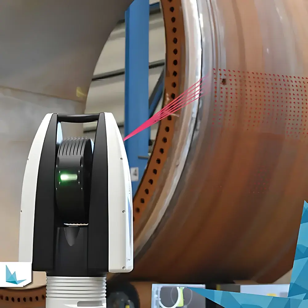
Leica ATS600 Absolute Laser Tracker
| Brand | Leica |
|---|---|
| Origin | Switzerland |
| Model | ATS600 |
| Max Measurement Range | 80 m |
| Horizontal Rotation | 360° |
| Vertical Pitch | ±145° |
| IP Rating | IP54 |
| Operating Temperature | 0 °C to +40 °C |
| Relative Humidity | ≤95% (non-condensing) |
| Laser Class | IEC 60825-1:2014 Ed.2 Class 2 |
| Environmental Monitoring | Integrated temperature, pressure & humidity sensors |
Overview
The Leica ATS600 Absolute Laser Tracker is an industrial-grade metrology system engineered for high-accuracy, large-volume 3D coordinate measurement and non-contact surface scanning. Unlike conventional laser trackers that rely exclusively on retroreflector targets (e.g., spherically mounted retroreflectors or SMRs), the ATS600 integrates an absolute distance meter (ADM) with a high-resolution panoramic imaging system and a precision angular encoder architecture—enabling true targetless scanning from distances up to 80 meters. Its core measurement principle combines interferometric and absolute distance measurement techniques with real-time stereo vision-based spatial registration, allowing direct digitization of freeform surfaces without physical contact or auxiliary tooling. Designed for aerospace, energy, heavy machinery, and automotive manufacturing environments, the ATS600 supports both dynamic alignment verification and static geometric inspection under demanding shop-floor conditions.
Key Features
- Absolute Targetless Scanning: Eliminates dependency on SMRs or handheld probes; captures dense point clouds directly from bare metal, composite, or painted surfaces using integrated ADM and panoramic camera fusion.
- Hybrid Measurement Architecture: Seamlessly switches between reflector-based single-point measurement (with PowerLock™ auto-reacquisition) and continuous area scanning—within the same software workflow and coordinate frame.
- Configurable Scan Parameters: Users define point density, scan speed, and region-of-interest (ROI) either via on-device panoramic preview or offline in Leica Metrology Software (LMS), enabling optimization for throughput vs. resolution trade-offs.
- Ruggedized Industrial Design: IP54-rated enclosure ensures operational reliability in dusty, humid, or temperature-fluctuating production environments; built-in environmental monitoring continuously logs ambient temperature, barometric pressure, and relative humidity for thermal compensation traceability.
- Autonomous Operation Support: Integrated rechargeable battery, Wi-Fi 5 (802.11ac), and Bluetooth 5.0 enable cordless deployment and remote control; gravity alignment and self-leveling mechanisms reduce setup time and operator dependency.
- Full-System Integration: All subsystems—including laser source, motorized azimuth/elevation stages, imaging sensor, ADM, and environmental sensors—are co-located within a single monolithic housing, minimizing thermal drift and mechanical misalignment risks.
Sample Compatibility & Compliance
The ATS600 is compatible with machined metallic components, carbon-fiber reinforced polymer (CFRP) assemblies, castings, forgings, and coated or anodized surfaces typical in aircraft fuselage sections, wind turbine blades, ship hull segments, and large-scale tooling. It complies with ISO 10360-12 (Acceptance and reverification tests for laser trackers), ISO 17025:2017 (General requirements for competence of testing and calibration laboratories), and supports audit-ready documentation per AS9100 Rev D and NADCAP AC7101/1. The Class 2 laser system meets IEC 60825-1:2014 Ed.2 requirements for eye safety under normal operating conditions; no laser safety officer (LSO) supervision is required for routine use.
Software & Data Management
The ATS600 operates exclusively with Leica’s Metrology Software (LMS) v6.x or later—a modular, Windows-based platform supporting GD&T evaluation, best-fit alignment, deviation mapping, and statistical process control (SPC) reporting. LMS provides native integration with common CAD formats (STEP AP242, IGES, JT), enables real-time point cloud streaming to third-party analysis tools via TCP/IP socket interface, and maintains full audit trails compliant with FDA 21 CFR Part 11 and ISO/IEC 17025 data integrity requirements. All measurement sessions include embedded metadata: timestamp, environmental readings, instrument status flags, and user authentication logs.
Applications
- Aerospace: Wing spar straightness verification, wingbox assembly alignment, and fuselage skin contour validation against master tooling.
- Energy: Dimensional verification of turbine blade root geometry, generator stator ring concentricity, and offshore platform structural node positioning.
- Automotive: Body-in-white (BIW) dimensional stability monitoring, stamping die wear analysis, and battery module tray flatness certification.
- Heavy Industry: Coordinate-based inspection of hydroelectric turbine runners, railcar bogie frame squareness, and shipbuilding block alignment prior to welding.
- Research & Development: Reverse engineering of legacy parts, validation of additive-manufactured lattice structures, and thermal deformation tracking during environmental chamber testing.
FAQ
Does the ATS600 require external reflectors for all measurements?
No—the ATS600 performs high-density surface scanning without any physical targets. Reflector-based measurement remains available for high-accuracy single-point verification or dynamic tracking applications.
Can the ATS600 be used outdoors?
It is rated IP54 and designed for controlled indoor industrial environments. Extended outdoor use is not recommended due to sensitivity to atmospheric turbulence, direct sunlight interference, and condensation risk beyond specified humidity limits.
Is thermal compensation automated?
Yes—integrated environmental sensors feed real-time temperature, pressure, and humidity data into LMS, which applies NIST-traceable atmospheric correction algorithms per ISO 10360-12 Annex B.
What CAD file formats are supported for nominal comparison?
STEP AP242, IGES, JT, VDA-FS, and native CATIA/Creo/NX exports are fully supported; mesh-based comparisons (STL) are enabled via optional add-on modules.
How is measurement uncertainty validated?
Uncertainty budgets follow ISO/IEC Guide 98-3 (GUM) methodology and are documented in the factory calibration certificate, which includes volumetric performance test results traceable to PTB (Physikalisch-Technische Bundesanstalt) standards.