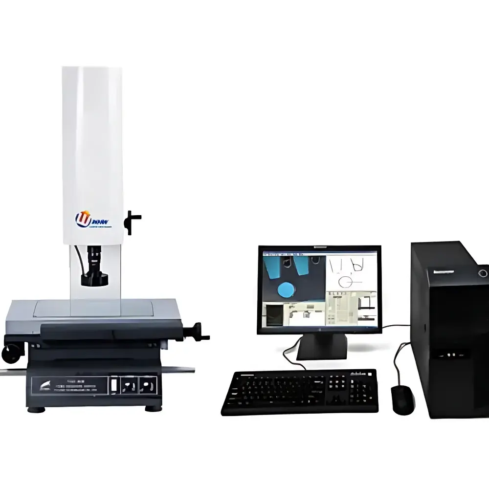
YANRUN YR-T2010 Economical Vision Measuring Machine
| Brand | YANRUN |
|---|---|
| Origin | Shanghai, China |
| Manufacturer Type | Direct Manufacturer |
| Region Classification | Domestic (China) |
| Model | YR-T2010 |
| Price | USD 1 (Base Unit Reference Only) |
| Table Surface (Metal) | 404 × 228 mm |
| Glass Stage Dimensions | 260 × 160 mm |
| Travel Range (X×Y) | 200 × 100 mm |
| Overall Dimensions (W×D×H) | 600 × 550 × 920 mm |
| Z-Axis Vertical Travel | 200 mm |
| Working Distance | 92 mm |
| Digital Readout Resolution (X/Y/Z) | 0.0005 mm |
| Positioning Accuracy (X/Y) | ≤(3 + L/200) µm |
| Camera | Color 1/3" CCD |
| Zoom Objective Magnification | 0.7× to 4.5× |
| Total Video Magnification | 30× to 230× |
| Object Field of View | 7.0 mm to 1.1 mm |
| Illumination | Dual LED (Top Surface & Bottom Transmitted), Adjustable Brightness |
| Power Supply | AC 180–260 V, 50 Hz |
| Standard Software | Automated 2D metrology suite with edge detection, deburring, geometric feature extraction (points, lines, circles, circle center distance, part alignment), and coordinate system registration |
Overview
The YANRUN YR-T2010 Economical Vision Measuring Machine is a precision 2D coordinate metrology system engineered for cost-sensitive quality control laboratories, contract manufacturing facilities, and R&D workshops requiring traceable geometric measurements without the complexity or capital investment of high-end CNC-based systems. It operates on the principle of optical triangulation and digital image correlation: a high-resolution 1/3″ color CCD sensor captures magnified images of parts placed on a rigid granite- or steel-reinforced stage; real-time video is processed through calibrated pixel-to-micron mapping to extract dimensional data. The system integrates a continuously variable zoom objective (0.7×–4.5×), enabling seamless transitions between wide-field inspection (7.0 mm FOV) and fine-feature resolution (1.1 mm FOV), while maintaining parfocal stability across magnifications. Its mechanical architecture features hardened linear guideways and a thermally stable base structure, minimizing drift during extended measurement cycles. Designed for ISO 9001-aligned environments, the YR-T2010 supports foundational GD&T evaluation—including position, concentricity, parallelism, and profile—within its specified 200 mm × 100 mm measurement envelope.
Key Features
- High-stability mechanical platform with 300 kg load capacity stage (compatible with YR-T2010 configuration), ensuring minimal vibration-induced error during manual or semi-automated operation
- Dual independent LED illumination system: top-mounted diffuse surface light for contour contrast enhancement and bottom-mounted transmitted light for silhouette-based edge detection of transparent or thin-sectioned components
- 0.0005 mm digital encoder resolution on all three axes (X/Y/Z), supporting sub-micron repeatability in controlled ambient conditions (20 ± 1 °C, <50% RH)
- Calibrated accuracy of ≤(3 + L/200) µm per ISO 10360-7:2019 Annex B methodology—verified using certified step gauges and ball-bar artifacts
- Parfocal zoom optics eliminate refocusing when changing magnification, reducing operator dependency and measurement cycle time
- Z-axis travel of 200 mm accommodates parts up to 180 mm in height (accounting for 92 mm working distance and lens clearance), suitable for stacked assemblies and multi-level fixtures
Sample Compatibility & Compliance
The YR-T2010 accepts flat, rigid, or lightly fixtured parts with maximum footprint dimensions of 260 mm × 160 mm on the optical glass stage—or up to 404 mm × 228 mm on the peripheral metal table. It is routinely deployed for measuring stamped sheet metal components, PCB fiducials, machined housings, injection-molded connectors, and watch movement parts. While not certified to ISO/IEC 17025 as a standalone calibration instrument, its measurement uncertainty budget aligns with ASTM E29-23 rounding conventions and supports internal process validation per IATF 16949 clause 7.1.5.2. All software-generated reports include timestamped operator ID, environmental condition flags (if external sensors are integrated), and audit-ready metadata export (CSV/Excel). The system complies with CE electromagnetic compatibility (EMC Directive 2014/30/EU) and low-voltage safety (LVD Directive 2014/35/EU).
Software & Data Management
The included 2D metrology software provides an intuitive Windows-based interface with programmable measurement routines, batch reporting, and statistical process control (SPC) charting. Core algorithms implement adaptive thresholding and sub-pixel edge interpolation (Sobel + centroid fitting) to mitigate noise from surface texture or minor lighting non-uniformity. Measurement sequences can be saved as reusable templates—including auto-alignment via three-point registration—and exported in XML or PDF formats compliant with internal document control SOPs. Audit trails record every user action (e.g., “User_A modified tolerance band for Circle_5 at 2024-04-12T09:22:17Z”), satisfying basic GLP documentation requirements. Raw image capture (.BMP/.TIFF) and coordinate data (.CSV) are stored separately to preserve evidentiary integrity. No cloud connectivity or remote access capabilities are embedded—data residency remains fully on-premise.
Applications
- First-article inspection of automotive gaskets, bracket holes, and flange bolt patterns
- Verification of PCB pad geometry, solder mask openings, and fiducial placement accuracy
- Dimensional release testing of medical device plastic housings (e.g., IV pump casings, sensor enclosures)
- Tooling validation for progressive die sets and EDM electrodes prior to production ramp-up
- Educational use in metrology training labs for teaching fundamental concepts of magnification calibration, uncertainty propagation, and GD&T symbology interpretation
FAQ
Is the YR-T2010 compatible with third-party calibration artifacts such as Renishaw XL-80 or ZYGO interferometer standards?
Yes—its stage geometry and encoder linearity allow traceable verification using NIST-traceable step gauges, gauge blocks, and optical gratings. However, full volumetric compensation requires optional laser tracker integration, not included in base configuration.
Can the system measure features with surface roughness exceeding Ra 3.2 µm?
Edge detection reliability decreases above Ra 6.3 µm due to diffraction-limited contrast degradation; for such surfaces, tactile probing or confocal microscopy is recommended.
Does the software support automated pass/fail decision logic based on GD&T callouts?
Basic tolerance checking (±X, ØY, positional tolerance zones) is supported; advanced ASME Y14.5-2018 composite frame evaluation requires post-processing in dedicated GD&T analysis tools like PolyWorks or Metrolog X4.
What maintenance schedule is recommended for long-term accuracy retention?
Annual recalibration of camera calibration matrix and encoder gain coefficients is advised; biannual cleaning of optical path components (lens, prism, CCD window) using Class 100 cleanroom protocols ensures sustained MTF performance.