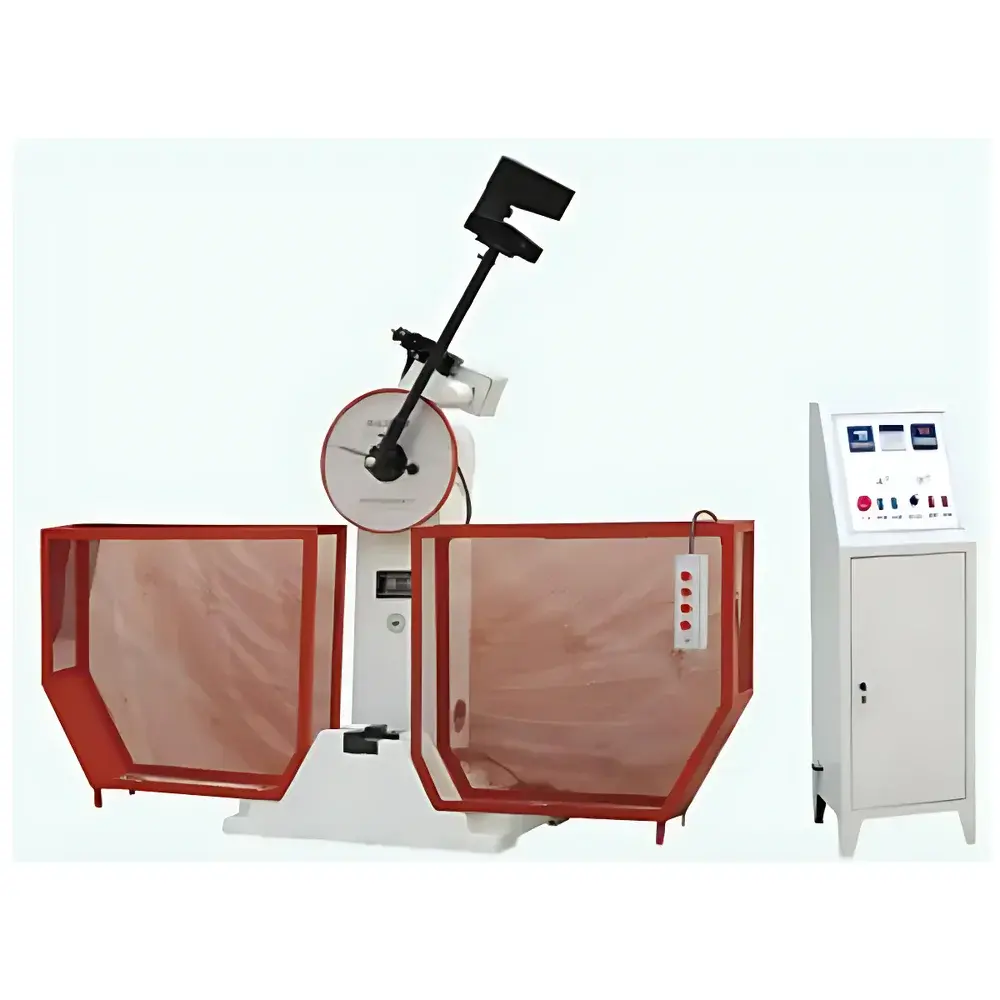
YANRUN JBS-500B Digital Semi-Automatic Pendulum Impact Testing Machine
| Brand | YANRUN |
|---|---|
| Origin | Shanghai, China |
| Manufacturer Type | Direct Manufacturer |
| Product Category | Domestic |
| Model | JBS-500B |
| Instrument Type | Pendulum Impact Tester |
| Impact Energy | 500 J (large hammer), 250 J (small hammer) |
| Impact Velocity | 5.4 m/s |
| Pendulum Lift Angle | 150° |
| Support Span | 40 mm |
| Anvil Radius | R1.0–R1.5 mm |
| Striking Edge Radius | R2.0–R2.5 mm |
| Distance from Pendulum Center to Impact Point | 800 mm |
| Standard Specimen Dimensions | 10 × 10 × 55 mm |
| Power Supply | 3-phase 4-wire, 50 Hz, 380 V |
| Angular Accuracy | ±0.1° |
| Mainframe Dimensions (L×W×H) | 2124 × 600 × 1340 mm |
| Digital Control Cabinet Dimensions (L×W×H) | 360 × 400 × 1200 mm |
| Net Weight | 450 kg |
| Environmental Requirements | Non-corrosive atmosphere, vibration-free installation site, absence of strong electromagnetic fields |
Overview
The YANRUN JBS-500B Digital Semi-Automatic Pendulum Impact Testing Machine is a precision-engineered instrument designed for standardized Charpy and Izod impact testing of metallic and polymeric materials in quality control, R&D, and certification laboratories. Operating on the classical pendulum principle—where gravitational potential energy is converted into kinetic energy upon release—the system delivers repeatable, traceable impact energy to standardized specimens under controlled mechanical conditions. The dual-hammer configuration (250 J and 500 J) enables compliance with ISO 148-1, ASTM E23, GB/T 229, and EN 10045-1 across a broad range of material toughness evaluations. Its semi-automatic architecture integrates motorized lifting, pneumatic or electromechanical auto-hanging, and fail-safe mechanical locking—reducing operator dependency while maintaining full mechanical integrity and metrological transparency.
Key Features
- Dual-capacity pendulum system with calibrated 250 J and 500 J hammers, each independently certified for energy accuracy per ISO 148-2 requirements.
- High-resolution angular encoder (±0.1° accuracy) ensures precise determination of pre-lift angle (150°) and residual swing angle—critical for energy calculation reproducibility.
- Optimized impact geometry: 800 mm effective pendulum length, 40 mm support span, and rigorously controlled anvil (R1.0–R1.5 mm) and striker (R2.0–R2.5 mm) radii to minimize stress concentration artifacts.
- Integrated safety architecture including mechanical interlocks, photoelectric beam sensors, reinforced polycarbonate shielding, and emergency stop circuitry compliant with IEC 60204-1.
- Touchscreen HMI controller with embedded PLC logic manages sequence execution—including automatic pendulum lifting, hanging, release, and post-impact data capture—without external PC dependency.
- Dedicated specimen alignment tools: centering gauge and support adjustment jig ensure strict adherence to standard specimen positioning tolerances (±0.2 mm lateral offset, ±0.1 mm height deviation).
- Modular design facilitates on-site maintenance; pendulum removal tool and quick-access service panels enable routine calibration verification and bearing inspection.
Sample Compatibility & Compliance
The JBS-500B accommodates standard Charpy V-notch (10 × 10 × 55 mm), U-notch, and keyhole specimens per ISO 148 and ASTM E23 specifications. Optional fixtures support sub-size specimens (e.g., 7.5 × 7.5 × 55 mm, 5 × 5 × 55 mm) when validated per ASTM E23 Annex A3. All mechanical components—including anvils, strikers, and supports—are manufactured from hardened tool steel (HRC ≥ 58) and surface-finished to Ra ≤ 0.4 µm to prevent premature wear-induced measurement drift. The system meets CE marking requirements for machinery safety (2006/42/EC), conforms to ISO/IEC 17025-relevant measurement uncertainty protocols, and supports audit-ready documentation for GLP and ISO 9001 environments.
Software & Data Management
Data acquisition and reporting are handled by the onboard touch interface running deterministic real-time firmware—not Windows-based software—ensuring immunity to OS-level instability. Each test record stores raw angular displacement vs. time traces, calculated absorbed energy (J), fracture appearance classification (ductile/brittle ratio), and operator ID/timestamp. Results export via USB to CSV or PDF formats; optional RS-485 or Ethernet interface enables integration into LIMS or MES platforms. Audit trail functionality logs all parameter modifications, calibration events, and user actions—supporting FDA 21 CFR Part 11 compliance when paired with institutional electronic signature policies.
Applications
- Quality assurance of structural steels, aluminum alloys, and weldments in aerospace, pressure vessel, and rail infrastructure manufacturing.
- Toughness screening of thermoplastics (e.g., ABS, PC, PEEK) and composites during formulation development and batch release.
- Low-temperature impact evaluation per ASTM D746 and ISO 974 using auxiliary environmental chambers (not included but compatible).
- Educational use in materials science laboratories for demonstrating ductile-to-brittle transition behavior.
- Third-party certification labs performing accredited testing per ISO/IEC 17025 scope requirements.
FAQ
What standards does the JBS-500B comply with for impact testing?
It supports ISO 148-1 (Charpy), ISO 148-2 (verification), ASTM E23, GB/T 229, and EN 10045-1 out-of-the-box, with traceable calibration certificates available upon request.
Is the system suitable for low-temperature testing?
Yes—when used with externally mounted environmental chambers (−80°C to +150°C), provided specimen transfer time and thermal soak conditions adhere to ASTM E23 Section 7.3.
How is energy calibration verified?
Calibration follows ISO 148-2 procedures using certified reference pendulums and independent angular measurement systems; annual verification by an ISO/IEC 17025-accredited lab is recommended.
Can test data be exported to laboratory information management systems (LIMS)?
Yes—via USB mass storage mode or optional serial/Ethernet communication modules supporting Modbus RTU/TCP protocols.
What maintenance intervals are recommended?
Lubrication of pivot bearings every 6 months, striker/anvil inspection after 500 impacts, and full mechanical verification annually—or per internal QA schedule aligned with ISO/IEC 17025 Clause 6.4.


