LaVision FlameMaster3D Volumetric 3D Flame Imaging System
| Brand | LaVision GmbH |
|---|---|
| Origin | Germany |
| Model | FlameMaster3D |
| Type | Tomographic Laser-Induced Fluorescence (LIF) and Chemiluminescence Imaging System |
| Configuration | Multi-camera or single-camera time-averaged volumetric acquisition |
| Compatible with | OH*, CH*, C₂*, and other flame radical emissions |
| Integrated with | FlowMaster Tomo PIV for concurrent 3D flow–flame coupling |
Overview
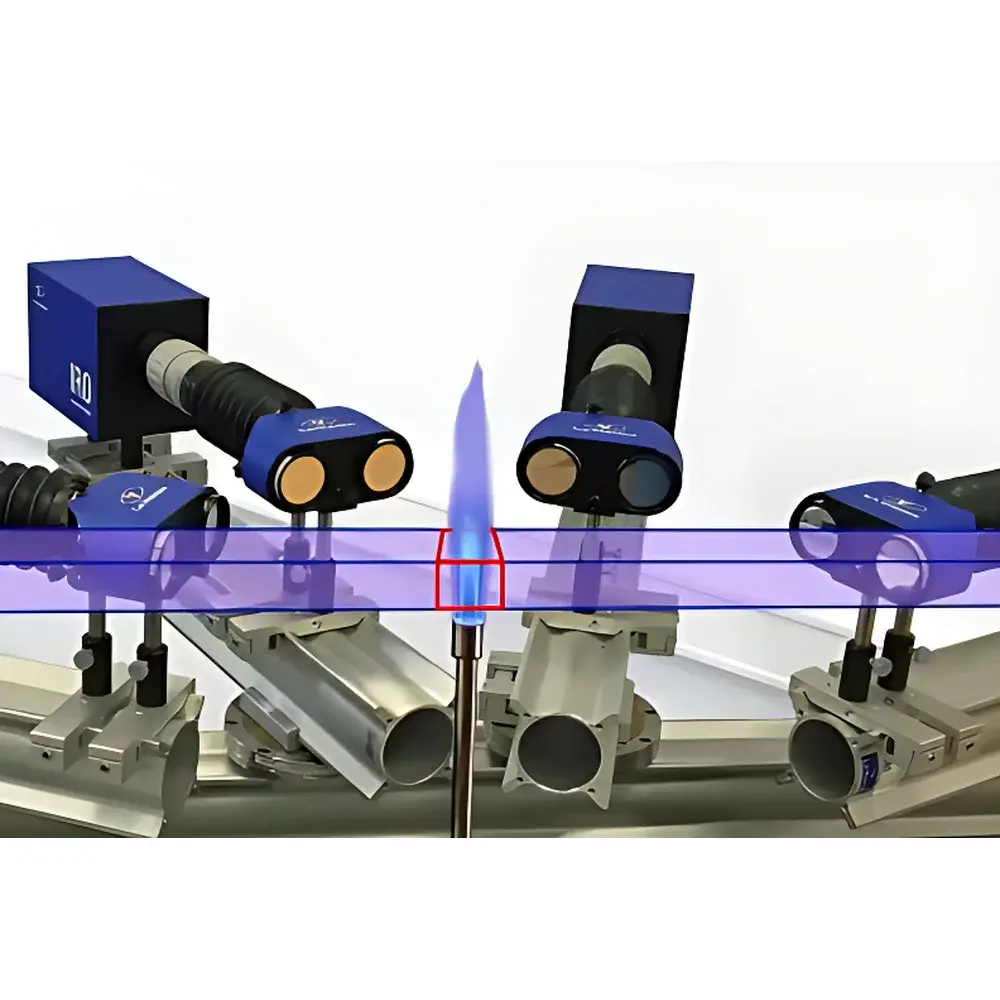
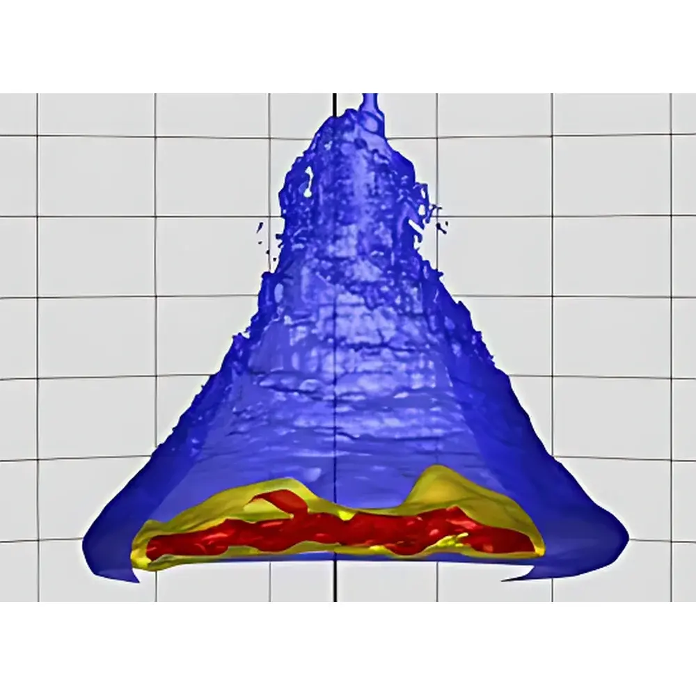
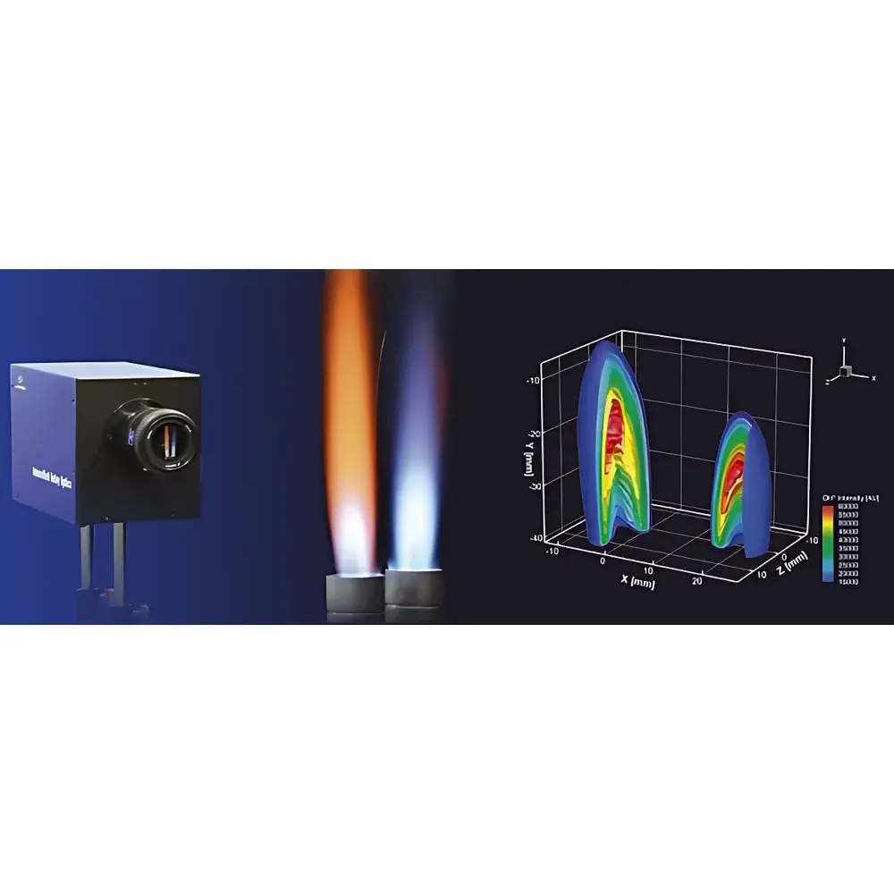
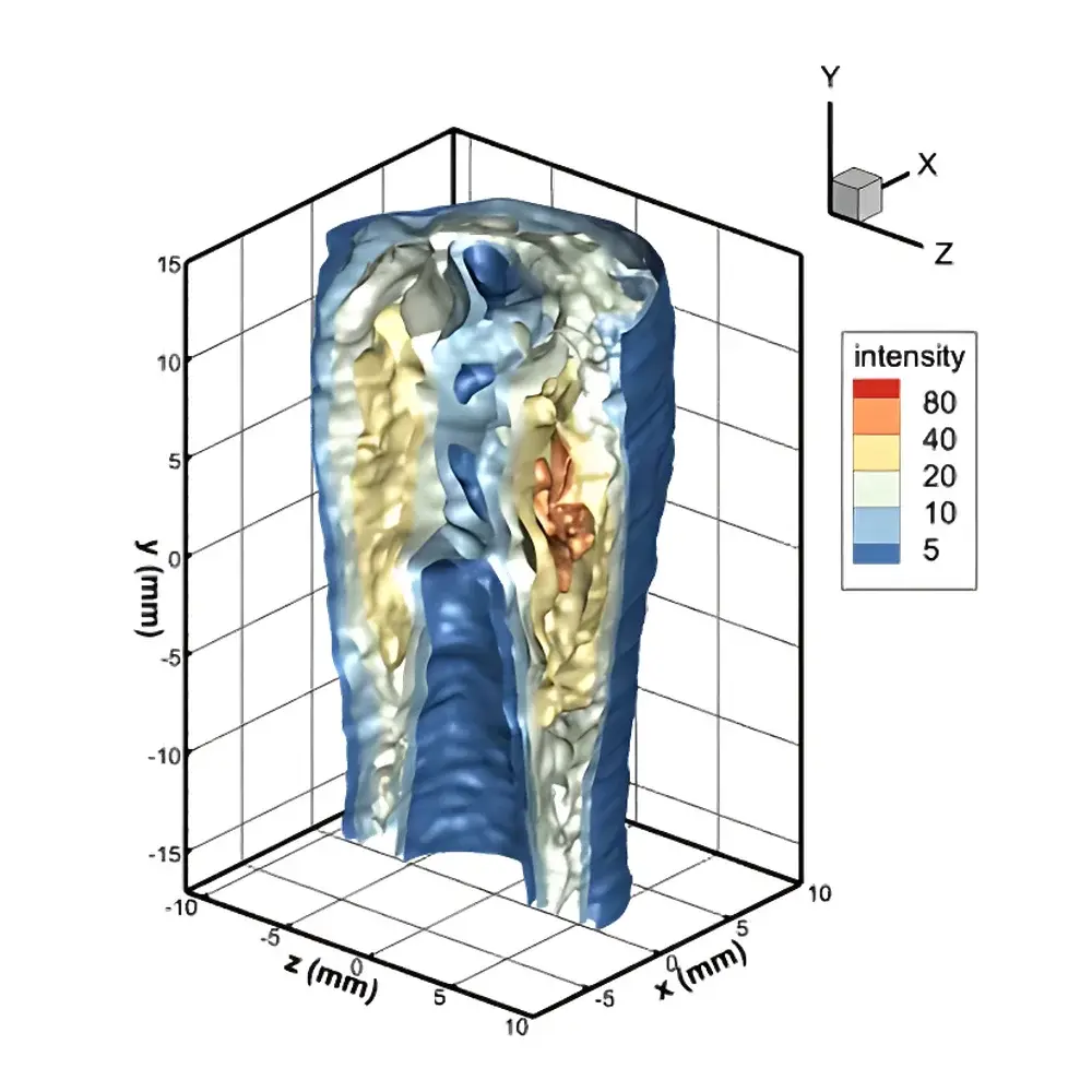
The LaVision FlameMaster3D is a high-fidelity volumetric 3D flame imaging system engineered for quantitative, spatially resolved analysis of reactive combustion structures in fundamental and applied research. It employs computed tomography principles to reconstruct three-dimensional distributions of chemiluminescent or laser-induced fluorescent (LIF) emission from combustion radicals—primarily hydroxyl (OH*), but also CH*, C₂*, and other species—within turbulent and laminar flames. Unlike planar or line-of-sight techniques, the FlameMaster3D captures true volumetric data without projection ambiguity, enabling rigorous validation of computational fluid dynamics (CFD) models, especially large-eddy simulation (LES) and direct numerical simulation (DNS) frameworks. The system supports two operational modes: (1) instantaneous 3D reconstruction using synchronized multi-camera acquisition (typically four intensified CCD/CMOS cameras equipped with image doublers), and (2) time-averaged 3D reconstruction via sequential single-camera imaging from multiple angular views under controlled rotational staging. This dual-mode architecture ensures flexibility across experimental constraints—including optical access, laser repetition rate, and data throughput requirements—while maintaining metrological traceability to NIST-traceable calibration standards.
Key Features
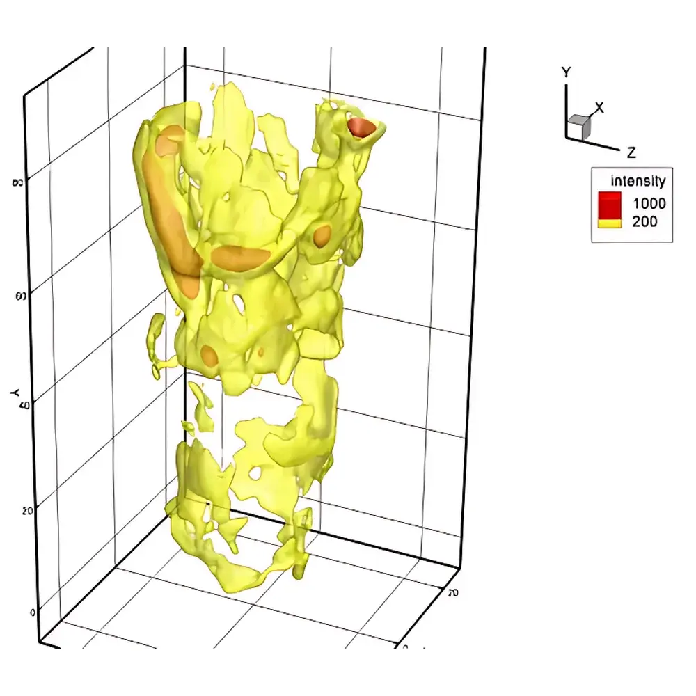
- Tomographic reconstruction engine optimized for low-SNR flame emission data, incorporating Tikhonov regularization and maximum likelihood estimation for robust 3D volume recovery
- Modular optical configuration supporting both chemiluminescence-only and LIF-based modalities, with wavelength-specific filters (e.g., 310 ± 5 nm for OH*, 431 ± 5 nm for CH*) and high-transmission dichroic beam splitters
- Real-time synchronization interface (TTL/RS-422) for precise coordination with pulsed lasers (Nd:YAG, excimer), high-speed shutter systems, and FlowMaster Tomo PIV illumination units
- Calibration suite including pinhole-array phantom targets, rotation-stage alignment routines, and camera-response homogenization protocols compliant with ISO 9001 laboratory procedures
- Rugged optomechanical design with kinematic mounts, thermal-stable aluminum breadboards, and modular lens adapters (C-mount, F-mount) for integration into existing combustion test rigs (e.g., Bunsen burners, swirl-stabilized combustors, gas turbine model chambers)
Sample Compatibility & Compliance
The FlameMaster3D is validated for use with atmospheric and pressurized (up to 10 bar) laminar and turbulent premixed, non-premixed, and partially premixed flames—including methane/air, propane/air, hydrogen/air, and syngas blends. It meets essential safety and electromagnetic compatibility requirements per EN 61326-1 (measurement control equipment) and EN 61000-6-3 (emission limits). Data acquisition workflows are compatible with GLP-compliant environments; metadata tagging (time stamp, laser energy, camera gain, filter ID, view angle) is embedded in HDF5-formatted output files to support auditability under FDA 21 CFR Part 11 when integrated with validated LabArchives or LabVantage ELN platforms. System calibration documentation adheres to ISO/IEC 17025:2017 clause 6.5 (traceability of measurements).
Software & Data Management
Acquisition and reconstruction are managed through DaVis 10.3+ software, featuring a dedicated FlameMaster3D module with GPU-accelerated tomographic inversion (CUDA-enabled), batch processing pipelines, and interactive 3D volume rendering (VTK-based). Raw images are stored in lossless TIFF or HDF5 format with embedded EXIF-style metadata. Reconstructed 3D volumes are exportable as ASCII grid files, VTK legacy formats, or NetCDF4 for direct ingestion into post-processing tools such as Tecplot, ParaView, or MATLAB. Software includes built-in uncertainty quantification modules estimating voxel-wise confidence intervals based on photon statistics and reprojection residuals. All user actions—including parameter changes, calibration steps, and reconstruction settings—are logged with timestamps and operator IDs to satisfy ALCOA+ (Attributable, Legible, Contemporaneous, Original, Accurate, Complete, Consistent, Enduring, Available) data integrity principles.
Applications
- Validation of turbulent combustion models by comparing experimentally derived 3D OH* concentration fields against simulated reaction zone topologies
- Quantitative assessment of local extinction and reignition events in lean-burn and MILD combustion regimes
- Coupled 3D flame–turbulence interaction studies using simultaneous FlameMaster3D and FlowMaster Tomo PIV acquisition
- Development and benchmarking of machine learning surrogates trained on high-resolution 3D flame datasets
- Evaluation of alternative fuel effects (e.g., ammonia, hydrogen blends) on flame topology, wrinkling factor, and scalar dissipation rates
FAQ
What laser sources are compatible with FlameMaster3D for OH-LIF?
Nd:YAG-pumped dye lasers (e.g., Coumarin 480, ~283 nm) or frequency-doubled OPOs operating at 283 nm are standard; tunability across 275–290 nm enables spectroscopic discrimination of OH rotational states.
Can FlameMaster3D be used without laser excitation?
Yes—chemiluminescence mode supports time-averaged 3D reconstruction of OH*, CH*, and C₂* emission using ambient flame radiation, provided sufficient signal-to-noise ratio and optical access.
Is tomographic reconstruction performed in real time?
Reconstruction is post-acquisition due to computational complexity; typical 128³ volume inversion requires 2–8 minutes on a workstation with dual NVIDIA A100 GPUs, depending on regularization depth and noise level.
How is geometric calibration verified across multiple views?
Using a precision-machined pinhole array phantom rotated incrementally through known angles; reprojection error is maintained below 0.3 pixels RMS across all camera views.
Does the system support synchronization with external PIV or PLIF systems?
Yes—via TTL trigger distribution hub and programmable delay generators; full hardware-level sync ensures sub-microsecond jitter between laser pulses, camera exposures, and PIV seeding timing.


