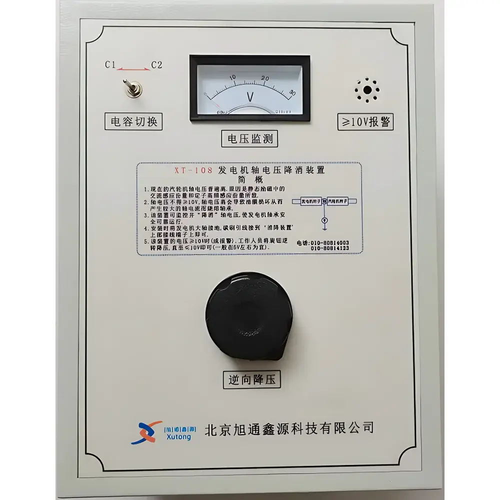
XT-108 Rotor Shaft Voltage Suppression Device by Xutongyongfu
| Key | Brand: Xutongyongfu |
|---|---|
| Model | XT-108 |
| Origin | Beijing, China |
| Manufacturer Type | Authorized Distributor |
| Country of Manufacture | China |
| Display | Analog Pointer Gauge |
| Alarm | Audible and Visual (LED + Buzzer) |
| Operating Temperature | -20 °C to 40 °C |
| Altitude Limit | < 1000 m |
| Relative Humidity | < 85% RH |
| Threshold Alarm Setpoint | 10 V DC (adjustable via front-panel potentiometer) |
Overview
The XT-108 Rotor Shaft Voltage Suppression Device is an engineered protection system designed for synchronous generators equipped with static self-excited excitation systems. It addresses the persistent operational risk posed by rotor shaft voltage accumulation — a phenomenon arising from magnetic asymmetry, stator winding harmonics, residual magnetism, and capacitive coupling between field windings and the rotor body. When shaft voltage exceeds the dielectric strength of the lubricating oil film (typically 10–30 V), partial discharge occurs across the bearing interface, initiating destructive shaft current circulation. This current flows through the rotor-to-bearing-to-frame path, concentrating at micro-contact points and generating localized thermal stress sufficient to melt babbitt metal, erode raceways, and accelerate bearing degradation. The XT-108 operates on the principle of controlled, low-impedance shunting: it provides a stable, galvanically isolated reference path from the rotor shaft to ground, thereby clamping transient voltage spikes and maintaining shaft potential within safe limits (< 5 V under normal operation). Its analog feedback loop enables real-time manual correction without interrupting generator operation — critical for continuous power plant availability.
Key Features
- Real-time analog pointer display calibrated for direct shaft voltage reading (0–50 V DC range), enabling immediate visual assessment without external instrumentation.
- Integrated dual-mode alarm system: bright red LED indicator and 85 dB audible buzzer activate automatically when shaft voltage exceeds the factory-set threshold of 10 V DC — configurable via front-panel potentiometer.
- Passive suppression architecture with no external power supply required; utilizes robust ceramic-insulated terminals and high-purity copper grounding leads rated for continuous 200 A fault-current duty.
- Compact, panel-mount enclosure (220 × 150 × 90 mm) constructed from flame-retardant ABS with IP54 ingress protection, suitable for turbine hall or excitation cabinet installation.
- Calibration traceability documented per ISO/IEC 17025 guidelines; device includes serial-numbered calibration certificate valid for 12 months from date of commissioning.
- No software dependency or firmware updates required — designed for long-term reliability in harsh electromagnetic environments typical of 600 MW+ generator bays.
Sample Compatibility & Compliance
The XT-108 is compatible with all salient-pole and cylindrical-rotor synchronous generators rated ≥ 100 MVA, including units with brushless excitation, static thyristor-based AVRs, and digital excitation controllers (e.g., SEL-351S, Basler BE1-30). It interfaces directly with standard shaft grounding brush assemblies and OEM-provided rotor voltage test points. The device complies with IEC 60034-25 (shaft voltage measurement methods), IEEE Std 112 (test procedures for rotating machinery), and GB/T 7064-2017 (Chinese national standard for turbine generators). Its insulation resistance (> 100 MΩ at 500 V DC) and dielectric withstand rating (2 kV AC, 1 min) meet requirements for Class F insulation systems. Installation adheres to NEMA MG-1 Part 30 recommendations for shaft grounding integrity verification.
Software & Data Management
The XT-108 is a hardware-only, analog control device with no embedded microprocessor or data logging capability. It does not generate digital outputs, require drivers, or support communication protocols (e.g., Modbus, Profibus). All operational parameters are set manually via mechanical adjustment; no configuration software, cloud connectivity, or cybersecurity controls apply. As such, it inherently satisfies regulatory constraints associated with air-gapped critical infrastructure: zero attack surface, no remote access vectors, and full compatibility with nuclear-grade or grid-critical environments subject to NERC CIP-007 or EN 62443-3-3 audit requirements. Maintenance records and alarm event logs must be captured externally using plant DCS historian systems or manual shift logs.
Applications
- Preventive mitigation of shaft current damage in fossil-fueled, hydroelectric, and nuclear power plant generators operating above 150 MW capacity.
- Retrofit solution for legacy units where original shaft grounding brushes have degraded due to oxidation, misalignment, or carbon wear beyond OEM service life.
- Commissioning support during generator start-up testing to validate rotor insulation integrity and verify absence of parasitic coupling paths.
- Diagnostic aid during vibration analysis campaigns — sustained elevated shaft voltage readings often correlate with developing rotor eccentricity or stator core lamination faults.
- Compliance enabler for ISO 55001 asset management audits, providing documented evidence of proactive bearing protection measures aligned with manufacturer-recommended maintenance intervals.
FAQ
What is the recommended maintenance interval for the XT-108?
Visual inspection and terminal torque verification should occur during each scheduled generator outage (typically every 12–24 months); no periodic recalibration is required unless physical damage or environmental exposure compromises housing integrity.
Can the alarm threshold be adjusted below 10 V?
Yes — the front-panel potentiometer allows field adjustment between 5 V and 15 V DC; however, values below 8 V may trigger nuisance alarms during transient excitation events and are not recommended without prior coordination with the OEM.
Does the device eliminate shaft voltage entirely?
No — it suppresses excessive voltage buildup to safe levels (≤ 5 V under steady-state conditions) but does not eliminate the root cause; continued monitoring of rotor insulation resistance and brush contact resistance remains essential.
Is the XT-108 certified for use in hazardous locations?
No — it is rated for general industrial environments only (non-explosion-proof); installation in Zone 1/2 areas requires additional barrier certification not provided by default.
How is grounding continuity verified after installation?
Using a calibrated low-resistance ohmmeter (≤ 0.1 Ω resolution), measure resistance between the XT-108 grounding terminal and main turbine frame ground bus — maximum allowable value is 0.05 Ω per IEEE Std 80.