YANRUN YR1401 Precision Autocollimator
| Brand | YANRUN |
|---|---|
| Origin | Shanghai, China |
| Manufacturer Type | OEM Manufacturer |
| Country of Origin | China |
| Model | YR1401 |
| Price | USD 2,350 (FOB Shanghai) |
| Working Distance | 0–6 m |
| Objective Focal Length | 400 mm |
| Objective Aperture | 42 mm |
| Eyepiece Magnification | 17.5× |
| Micrometer Drum Graduation | 1.04 arcsec per division (≈1″), linear equivalent = L/200 µm (L = mirror base length in mm) |
| Reticle Scale Graduation | 100× micrometer resolution |
| Total Scale Range | 1600 divisions |
| Accuracy | ±(0.5 + 0.01n) divisions (n ≤ 100) |
| Dimensions (L×W×H) | 254 × 57 × 157 mm |
Overview
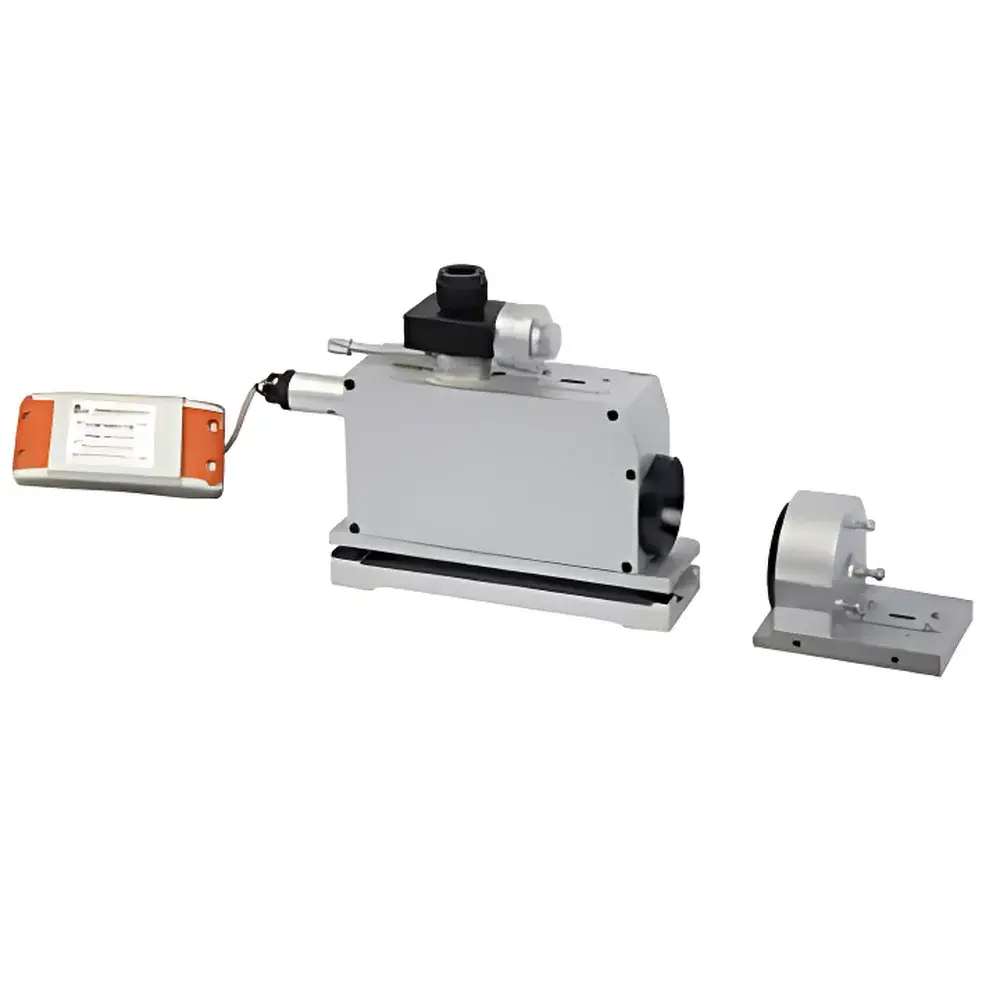
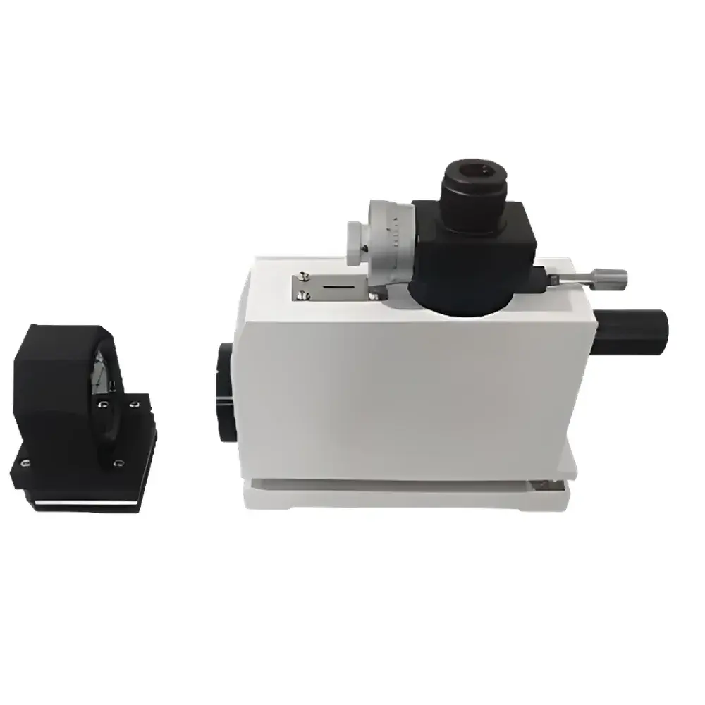
The YANRUN YR1401 Precision Autocollimator is an optomechanical metrology instrument engineered for high-accuracy angular and linear displacement measurement based on the principle of optical autocollimation. It employs a collimated light beam directed onto a reflective surface—typically a plane mirror mounted on the object under test—and analyzes the angular deviation of the returned retroreflected image within a calibrated eyepiece reticle or digital imaging sensor path. This non-contact method enables traceable, drift-resistant measurement of straightness, flatness, angular alignment, and rotational error motion in machine tool guideways, precision granite tables, optical benches, and calibration artifacts. Designed for laboratory-grade metrology and shop-floor verification, the YR1401 delivers sub-arcsecond angular resolution (1.04″ per division) with full-scale angular range exceeding ±800″ (±0.004°), making it suitable for ISO 230-1/2-compliant machine tool performance verification and ASTM E2921-compliant optical alignment validation.
Key Features
- Compact monolithic optical architecture: 254 mm × 57 mm × 157 mm aluminum alloy housing ensures mechanical stability and thermal homogeneity during extended measurements.
- Dual-mode readout capability: Analog micrometer drum (17.5× eyepiece magnification) with 1.04″/division resolution, complemented by optional digital camera integration for automated centroid tracking and real-time data logging.
- Extended working distance range: Optimized 400 mm focal-length objective with 42 mm clear aperture supports reliable operation from contact to 6 m—enabling large-structure alignment without repositioning.
- Modular accessory interface: Standard M6 threaded mounting points and kinematic base geometry allow seamless integration with magnetic mirrors, optical right-angle prisms, polygon calibrators, and laser alignment aids.
- Traceable calibration support: Supplied with NIST-traceable angular calibration certificate (optional); compatible with ISO 10360-8 and VDI/VDE 2617 Part 6 verification protocols.
Sample Compatibility & Compliance
The YR1401 is routinely deployed in accredited metrology labs (ISO/IEC 17025), machine tool OEM quality assurance departments, and academic precision engineering facilities. Its measurement methodology conforms to fundamental principles outlined in ISO 10110-1 (optical component tolerancing), ISO 230-1 (machine tool geometric accuracy), and GB/T 17421.1 (Chinese national standard equivalent to ISO 230-1). When used with certified reference mirrors (surface flatness λ/20 @ 633 nm) and calibrated multi-faceted polygons, the system supports uncertainty budgets compliant with GUM (JCGM 100:2008) for angular error mapping. The instrument requires no external vacuum or climate-controlled enclosure but must be operated on vibration-isolated optical tables or granite slabs in environments meeting ISO 22959 Class 2 (temperature stability ±1°C/h, humidity 40–60% RH, absence of air turbulence).
Software & Data Management
While the base YR1401 operates as a manual analog instrument, its modular design supports third-party digitalization via C-mount adapter (optional). When paired with a CMOS line-scan or area-scan camera (e.g., Basler acA1300-60gm), the system interfaces with open-architecture software platforms including MATLAB Instrument Control Toolbox, Python-based OpenCV pipelines, or commercial metrology suites such as PolyWorks Inspector or Q-DAS qDAS. All digital configurations support audit-trail-enabled data export in CSV, XML, and HDF5 formats, with timestamped metadata (operator ID, environmental conditions, calibration status) to satisfy FDA 21 CFR Part 11 and GLP/GMP documentation requirements. Firmware-upgradable controllers (available as MC030 series add-on) provide USB 2.0 and Ethernet connectivity, real-time compensation for temperature-induced focal shift, and automated drift correction algorithms.
Applications
- Machining center guideway straightness verification (horizontal and vertical planes) per ISO 230-2 Annex B.
- Rotary table indexing error analysis using polygon reflectors (up to 72 faces) and harmonic decomposition.
- Optical axis collimation of telescope mounts, interferometer arms, and laser resonators.
- Flatness assessment of precision granite surfaces via grid-based autocollimation scanning.
- Dynamic tilt monitoring of seismic isolation platforms using high-frame-rate camera coupling.
- Educational demonstration of wavefront tilt, Abbe error propagation, and sensitivity amplification in angular metrology.
FAQ
What is the minimum measurable angular deviation with the YR1401?
The instrument achieves a base resolution of 1.04 arcseconds per division on the micrometer drum; with interpolation and digital centroid fitting, effective resolution improves to ≤0.3 arcseconds.
Can the YR1401 measure both horizontal and vertical deviations simultaneously?
Yes—the dual-axis reticle scale and orthogonal adjustment mechanism allow independent quantification of pitch and yaw components within a single setup.
Is the YR1401 compatible with international calibration standards?
Yes—it supports traceability to CIPM MRA signatory NMIs via optional calibration against angle blocks or laser interferometric angle comparators per ISO 10012.
Does the system require periodic recalibration?
Annual verification against a certified reference mirror is recommended; drift testing per ISO 10012-2 should be performed before critical measurements.
What accessories are required for measuring perpendicularity between two axes?
An optical right-angle prism (e.g., 90° ±0.5″ fused silica cube) and magnetically mounted reference mirror are mandatory; both are available as factory-qualified options.