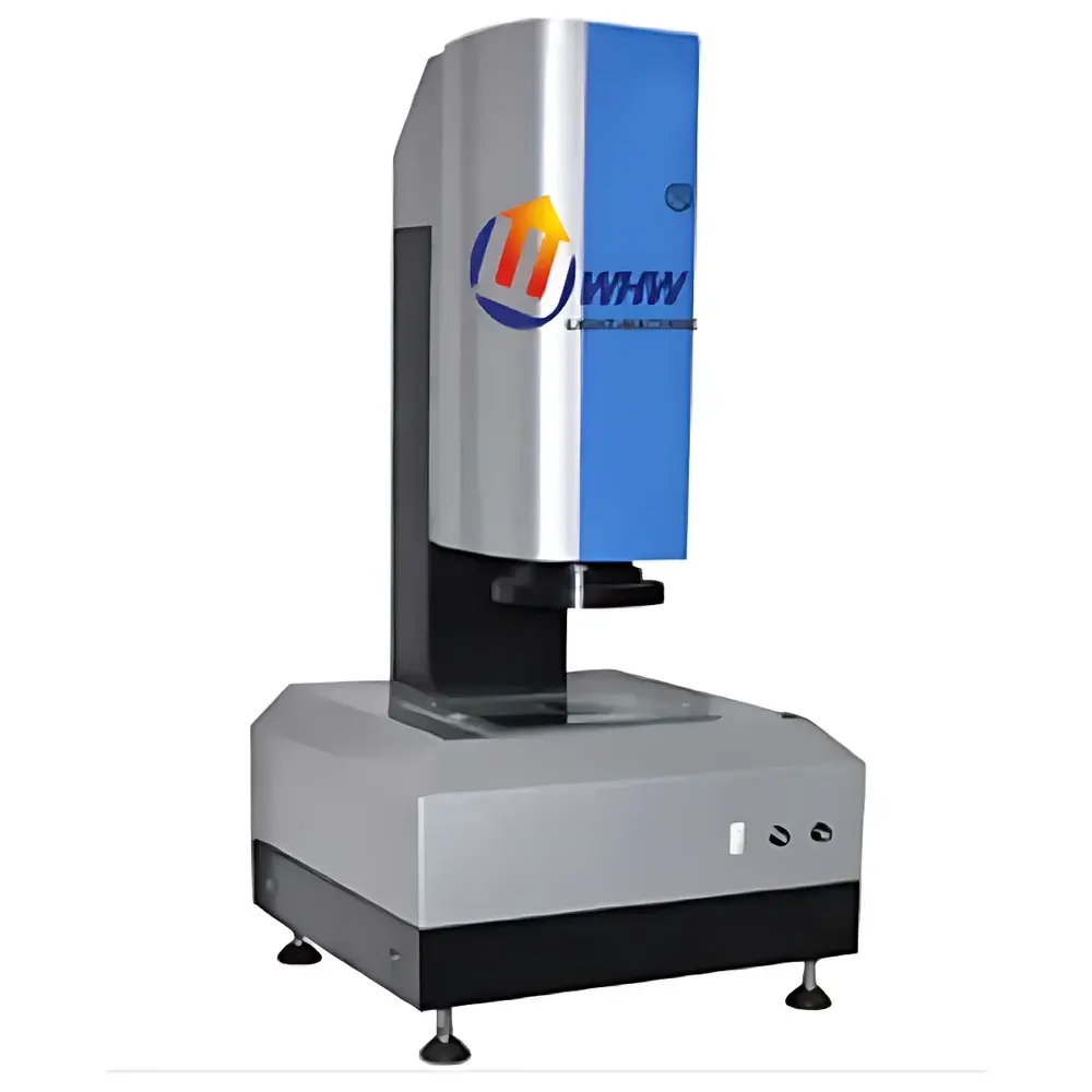
YANRUN YR-100I High-Throughput Batch Image Measuring System
| Brand | YANRUN |
|---|---|
| Origin | Shanghai, China |
| Manufacturer Type | OEM Manufacturer |
| Country of Origin | China |
| Model | YR-100I |
| Operation Mode | Fully Automatic |
| Image Sensor | 1/1.8" 5 MP CCD |
| Telecentric Lens Magnification | 0.138X |
| Measurement Field of View | 96 mm × 72 mm |
| Repeatability Accuracy | ±0.01 mm |
| Working Height | 200 mm |
| Illumination | Collimated Parallel Light Source |
| Dimensions (W×D×H) | 550 mm × 400 mm × 895 mm |
Overview
The YANRUN YR-100I High-Throughput Batch Image Measuring System is an industrial-grade optical coordinate measuring instrument engineered for rapid, non-contact geometric metrology in high-volume production environments. Based on telecentric imaging and sub-pixel edge detection algorithms, the system captures full-field 2D images of multiple parts simultaneously and performs automated dimensional analysis—including length, width, diameter, angle, position, and profile deviation—against GD&T tolerances or imported CAD reference geometry. Unlike traditional stage-scanning vision systems, the YR-100I eliminates mechanical XY motion during measurement; instead, it relies on a fixed-stage design with a large-format telecentric lens and high-resolution CCD sensor to achieve consistent magnification across the entire 96 mm × 72 mm field of view. This architecture ensures stable optical path geometry, minimizes parallax error, and supports repeatable measurements at ±0.01 mm uncertainty under controlled ambient conditions—meeting ISO 10360-7 and VDI/VDE 2634 Part 3 requirements for image-based coordinate measuring systems.
Key Features
- Fully automated measurement cycle: Complete acquisition, edge extraction, dimension calculation, and pass/fail evaluation in ≤2 seconds per batch—enabling up to 1,800 inspections/hour under continuous operation.
- Multi-part simultaneous inspection: Load up to 6–12 small components (e.g., M2–M6 screws, smartphone glass cutouts, gear blanks) onto the stationary platform without fixturing; all are imaged and evaluated in a single frame.
- Direct CAD-to-part comparison: Import DXF or STEP files to overlay nominal geometry; deviations (e.g., burr presence, oversize/undersize features, positional offset) are color-coded and quantified in real time.
- Collimated parallel illumination: Uniform, shadow-free backlighting and coaxial surface lighting ensure high-contrast edge definition for both transparent and opaque materials—including tempered glass, stainless steel, and injection-molded polymers.
- Telecentric optical path: 0.138X magnification lens with 1/1.8″ 5-megapixel CCD delivers distortion-free imaging across full FOV, supporting traceable calibration via NIST-traceable step gauges or certified artifact plates.
Sample Compatibility & Compliance
The YR-100I is optimized for planar, rigid components with maximum height ≤20 mm and footprint within 96 mm × 72 mm. Typical applications include precision stampings, miniature gears, PCB connectors, watch components, medical micro-parts, and consumer electronics housings. The system complies with ISO 17025 documentation practices for calibration records and supports audit-ready reporting aligned with IATF 16949 clause 7.1.5.2 (Measurement Traceability) and ISO 9001:2015 clause 8.5.1 (Control of Production and Service Provision). All measurement data logs include timestamp, operator ID, environmental temperature (via optional external probe), and instrument serial number—facilitating GLP/GMP-compliant record retention.
Software & Data Management
The embedded Windows-based metrology software provides intuitive workflow configuration: define measurement routines via point-and-click geometry tools, set tolerance limits per feature, assign pass/fail logic, and generate exportable reports in native Microsoft Word (.docx) and Excel (.xlsx) formats—including statistical summaries (Cp/Cpk, X-bar R charts) and annotated image overlays. Audit trails record all user actions, parameter changes, and report generations in accordance with FDA 21 CFR Part 11 requirements when configured with electronic signature modules. Data export supports SPC integration via OPC UA or CSV streaming for MES/SCADA connectivity.
Applications
- Automotive Tier-1 suppliers: In-line verification of fastener thread runout, head flatness, and pitch diameter consistency.
- Consumer electronics OEMs: 100% incoming inspection of smartphone camera lens holders, SIM tray cutouts, and fingerprint sensor apertures.
- Medical device manufacturers: Dimensional validation of surgical clip dimensions, catheter hub features, and microfluidic channel widths.
- Watchmaking and jewelry: Profile matching of gear train components and bezel engravings against master templates.
- Quality laboratories: Rapid first-article inspection (FAI) with full GD&T reporting per ASME Y14.5–2018 standards.
FAQ
Does the YR-100I require manual focusing or lens calibration between batches?
No. The telecentric lens and fixed-focus optical path eliminate focus drift; calibration is performed once during installation using certified artifacts and remains valid unless physically disturbed.
Can the system measure features with curved surfaces or angled edges?
It is designed for planar, top-down 2D measurement only. Curved or inclined features must be presented orthogonally to the optical axis; for true 3D form analysis, a structured-light or laser line scanner is recommended.
Is third-party calibration certification available?
Yes. Accredited calibration services compliant with ISO/IEC 17025 are offered by authorized YANRUN service centers, including uncertainty budgets per ISO/IEC 17025:2017 Annex A.3.
What file formats are supported for CAD import?
DXF (R12–R2018), DWG (via AutoCAD RealDWG engine), and STEP AP203/AP214 files can be imported and aligned using manual or auto-feature-based registration.
How is measurement uncertainty validated?
Uncertainty is determined per ISO/IEC Guide 98-3 (GUM) using Type A (repeatability studies over ≥30 measurements) and Type B (lens MTF, pixel size, calibration artifact uncertainty) components, documented in the system’s Certificate of Conformance.