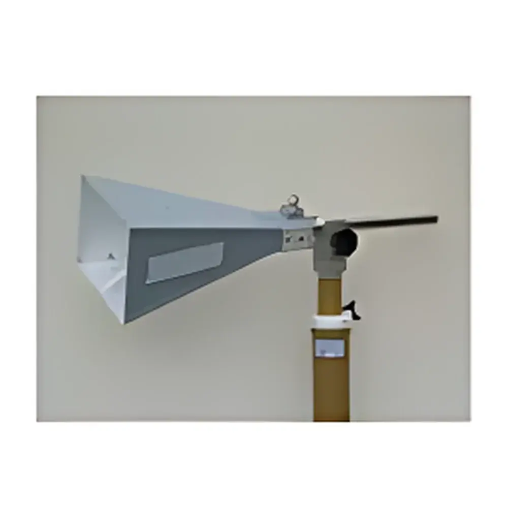
EMC Test Solutions Horn Antenna Model HX-6G – 1–6 GHz High-Power Broadband Directive Antenna
| Frequency Range | 1–6 GHz |
|---|---|
| Maximum Input Power | 300 W |
| Gain (at 3 m distance) | 12.48 dBi @ 1 GHz |
| Origin | Italy |
| Type | Passive Wideband Horn Antenna |
| Compliance | Designed for EMC Radiated Emission & Immunity Testing per CISPR 16-1-4, ANSI C63.4, IEC 61000-4-3 |
Overview
The EMC Test Solutions HX-6G is a precision-engineered, passively operated broadband horn antenna optimized for radiated electromagnetic compatibility (EMC) testing in accredited laboratories and industrial compliance facilities. Operating on the fundamental principle of aperture-fed directional radiation, the HX-6G leverages a flared metallic waveguide structure to achieve controlled beamwidth, stable phase center, and minimal sidelobe generation across its full 1–6 GHz frequency band. Its design adheres to the physical constraints and calibration traceability requirements defined in CISPR 16-1-4 for measurement antennas used in radiated emission and immunity test setups. The antenna is calibrated with free-space far-field reference data traceable to national metrology institutes (e.g., INRIM, Italy), ensuring repeatability and inter-laboratory comparability under standardized test configurations (e.g., 3 m or 10 m semi-anechoic chamber environments). Unlike resonant or narrowband alternatives, the HX-6G maintains consistent impedance matching (VSWR ≤ 1.5:1 typical) and polarization purity (linear, vertical/horizontal configurable) without retuning—enabling efficient sweep-based emissions scans and robust immunity field generation.
Key Features
- High-power handling capability: Rated for continuous-wave (CW) input up to 300 W, supporting both emission diagnostics and high-field immunity testing (e.g., IEC 61000-4-3 Level 3–4).
- Stable gain profile: Characterized gain values (12.48 dBi @ 1 GHz, 15.54 dBi @ 3 GHz, 18.77 dBi @ 6 GHz) are validated at 3 m distance using calibrated reference sources and normalized to NIST-traceable standards.
- Robust mechanical architecture: CNC-machined aluminum housing with gold-plated internal surfaces minimizes insertion loss and ensures long-term RF stability under thermal cycling and repeated mounting cycles.
- Standardized mounting interface: 7/16 DIN female connector with integrated torque-limiting flange enables secure, repeatable installation on turntables and positioners compliant with ISO/IEC 17025 laboratory practices.
- Low passive intermodulation (PIM) performance: Optimized contact geometry and surface finish suppress PIM generation below –140 dBc (two-tone, 2 × 20 W), critical for multi-carrier immunity testing scenarios.
Sample Compatibility & Compliance
The HX-6G is compatible with all standard EMC test receivers, spectrum analyzers, and RF signal generators equipped with 50 Ω coaxial interfaces. It supports both horizontal and vertical polarization via 90° rotational symmetry and optional tilt-mount adapters. The antenna meets the geometric and electrical criteria specified in CISPR 16-1-4 Annex D for broadband antennas used in radiated emission measurements up to 6 GHz. For immunity applications, it satisfies field uniformity requirements (±3 dB over 1.5 × 1.5 m test plane) when driven by amplifiers compliant with IEC 61000-4-3 Annex A. Calibration certificates include full gain vs. frequency curves, VSWR plots, and pattern cuts (E- and H-plane), delivered with ISO/IEC 17025-accredited uncertainty budgets (k = 2). All units are supplied with EU Declaration of Conformity (DoC) referencing Directive 2014/30/EU (EMC Directive).
Software & Data Management
While the HX-6G operates as a passive transducer, its performance data integrates seamlessly into automated EMC test systems via industry-standard instrument drivers (IVI-COM, SCPI over LAN/GPIB). Gain correction factors and antenna factor (AF) tables are preloaded into major test software platforms—including Keysight PathWave EMPro, Rohde & Schwarz EMC32, and TESEQ NSG 438—enabling real-time emission limit comparison and margin analysis. Raw calibration datasets (S11, gain, AF) are provided in CSV and MATLAB-compatible .mat formats for custom post-processing and GLP-compliant audit trails. All delivered documentation conforms to FDA 21 CFR Part 11 requirements for electronic records, including digital signatures, version control, and change logs.
Applications
- Radiated emissions testing of IT equipment, automotive ECUs, and medical devices per EN 55032, CISPR 32, and ISO 11452-2.
- RF immunity validation for industrial control systems under IEC 61000-4-3, including field uniformity verification at 3 m and 10 m distances.
- Antenna pattern characterization and near-field-to-far-field transformation studies in metrology labs.
- Reference antenna use in inter-laboratory comparison exercises organized by ILAC MRA signatories.
- Support for wireless coexistence testing (e.g., Bluetooth/Wi-Fi interference assessment) where calibrated field strength reproducibility is essential.
FAQ
Is this antenna suitable for 10 m chamber testing?
Yes—the gain and pattern data are validated at 3 m, but extrapolation to 10 m is permitted per CISPR 16-1-4 Clause 7.3.2, provided chamber validation confirms field uniformity.
Does the antenna require periodic recalibration?
Yes—annual recalibration is recommended per ISO/IEC 17025 and manufacturer guidelines to maintain traceability and uncertainty compliance.
Can it be used with pulsed RF signals?
Yes—peak power handling exceeds 300 W for pulses ≤ 10 µs width and ≤ 10% duty cycle, subject to thermal derating per IEC 61000-4-3 Annex B.
Is an antenna factor (AF) table included?
Yes—each unit ships with a NIST-traceable AF curve (1–6 GHz, 10 MHz step resolution) and associated expanded uncertainty (k = 2) report.
What mounting accessories are available?
Standard options include azimuth-elevation positioner adapters, low-reflection mast clamps, and polarization rotators compliant with ANSI C63.4 Figure 7 specifications.


 for EMI Conducted Emission & Immunity Testing")