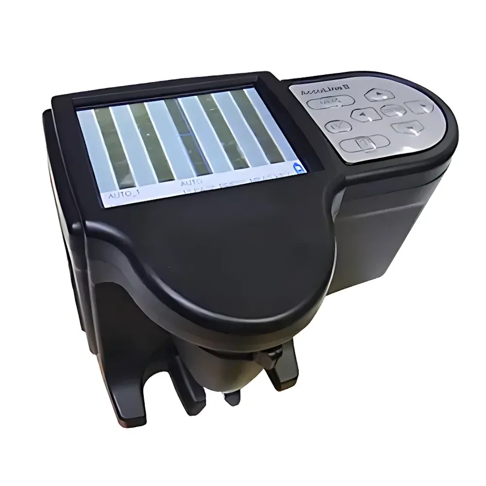
IHARA AccuLine II Digital Line Width Measurement System
| Brand | Ihara Electronic |
|---|---|
| Origin | Japan |
| Manufacturer Type | Authorized Distributor |
| Origin Category | Imported |
| Model | AccuLine II |
| Pricing | Available Upon Request |
| Light Source | White LED |
| Imaging Sensor | CMOS |
| Field of View | 1.28 × 0.96 mm |
| Measurement Accuracy | ±(1 + L/100) µm |
| Data Storage | 200 measurements (SD card, 2 GB included) |
| Display | 3.5-inch color LCD, 320 × 240 pixels |
| Charging Time | ~3 hours |
| Interface | USB |
| OS Compatibility | Windows XP / 7 |
| Dimensions | 160(L) × 110(D) × 118(H) mm |
Overview
The IHARA AccuLine II Digital Line Width Measurement System is a precision optical metrology instrument engineered for non-contact, high-resolution dimensional analysis of conductive traces on printed circuit boards (PCBs) and related microfabricated substrates. Operating on the principle of high-contrast digital image acquisition and sub-pixel edge detection, the system utilizes a calibrated white LED illumination source and a monochrome CMOS sensor to capture sharp, low-noise images of conductor cross-sections. Its dual-surface measurement capability enables simultaneous quantification of top-side and bottom-side trace widths—critical for evaluating etching uniformity, sidewall taper, and plating consistency in multilayer PCB manufacturing. Designed specifically for inline quality assurance and process validation labs, the AccuLine II delivers traceable, repeatable measurements within the 30–900 µm range for line width and up to 700 µm for through-hole (TH) diameters, supporting both automated pass/fail judgment and manual operator-guided analysis.
Key Features
- Dual-surface line width measurement: Simultaneous acquisition and analysis of conductor width at both top and bottom interfaces—essential for assessing etch profile symmetry and via wall integrity.
- Automated pass/fail decision engine: Configurable reference width and tolerance thresholds enable real-time GO/NO-GO classification directly on the 3.5-inch color LCD interface.
- Manual measurement mode: Supports precise operator-defined measurement of TH diameters and angular features (e.g., trace skew or pad alignment), with on-screen crosshair positioning and pixel-to-micron calibration retention.
- Embedded metrology-grade optics: Fixed-focus optical path with uniform white LED illumination ensures consistent contrast and minimal shadowing across the 1.28 × 0.96 mm field of view.
- On-device data management: Internal storage supports up to 200 measurement records; all data exportable via USB to SD card (2 GB supplied) for offline traceability and audit readiness.
- Portable, benchtop-ready design: Compact footprint (160 × 110 × 118 mm) and integrated rechargeable battery (3-hour charge cycle) facilitate deployment in cleanroom environments, QA labs, or production-floor stations.
Sample Compatibility & Compliance
The AccuLine II is optimized for rigid and flexible PCB substrates with surface finishes including ENIG, HASL, OSP, and immersion silver. It accommodates standard FR-4, polyimide, and ceramic-based boards up to 3.2 mm thickness. Measurement repeatability meets IPC-TM-650 2.2.17 requirements for optical line width verification. While not certified to ISO/IEC 17025 as a standalone calibration system, its accuracy specification (±(1 + L/100) µm) aligns with industry-accepted tolerances for Class II and III PCB inspection per IPC-A-600 and IPC-6012. All firmware and measurement algorithms are deterministic and version-locked—supporting GLP-compliant documentation workflows when paired with controlled data export procedures.
Software & Data Management
The system operates independently of host PC software during measurement but interfaces seamlessly with Windows XP and Windows 7 via USB for data retrieval and report generation. Measurement files are stored in plain-text CSV format with timestamp, operator ID (manually entered), XY coordinates, measured width values (top/bottom), TH diameter (if applicable), and PASS/FAIL status. The included CD-ROM contains a lightweight viewer application for histogram generation, batch statistics (mean, σ, Cp/Cpk), and export to Excel-compatible formats. No proprietary drivers or cloud connectivity are required—ensuring full data sovereignty and compatibility with air-gapped manufacturing IT environments subject to IEC 62443 or FDA 21 CFR Part 11 archival requirements.
Applications
- Final inspection of HDI and fine-pitch PCBs prior to solder mask application or assembly.
- In-process verification of etch rate uniformity across panel zones during mass production.
- Root cause analysis of conductor bridging, undercut, or over-etch defects in failure analysis labs.
- Qualification of new photolithography or direct imaging equipment by benchmarking line edge roughness (LER) trends.
- Supplier qualification audits requiring objective, operator-independent width verification against contractual specifications.
- Training and certification of QA technicians using standardized measurement protocols and reference artifacts.
FAQ
What is the smallest measurable line width, and how is resolution ensured?
The system reliably resolves features down to 30 µm, achieved through optimized pixel pitch, diffraction-limited optics, and sub-pixel interpolation algorithms validated against NIST-traceable step gauges.
Can the AccuLine II be integrated into an automated production line?
It functions as a semi-automated benchtop tool; integration with conveyorized handling requires custom fixture design and external triggering—no built-in PLC I/O or Ethernet port is provided.
Is calibration traceable to national standards?
Users perform periodic verification using certified line width standards (e.g., VLSI Standards SRM-1990); full calibration services are available through Ihara-authorized service centers in Japan and select APAC regions.
Does the system support measurement of curved or angled traces?
Yes—manual measurement mode allows freehand line placement and angular offset definition; however, automated width detection assumes straight-line geometry within the FOV.
How is data integrity maintained during export and long-term archiving?
All exported CSV files include embedded metadata (firmware version, calibration date, user input), and no data transformation occurs during USB transfer—preserving bit-for-bit fidelity required for internal audit trails.