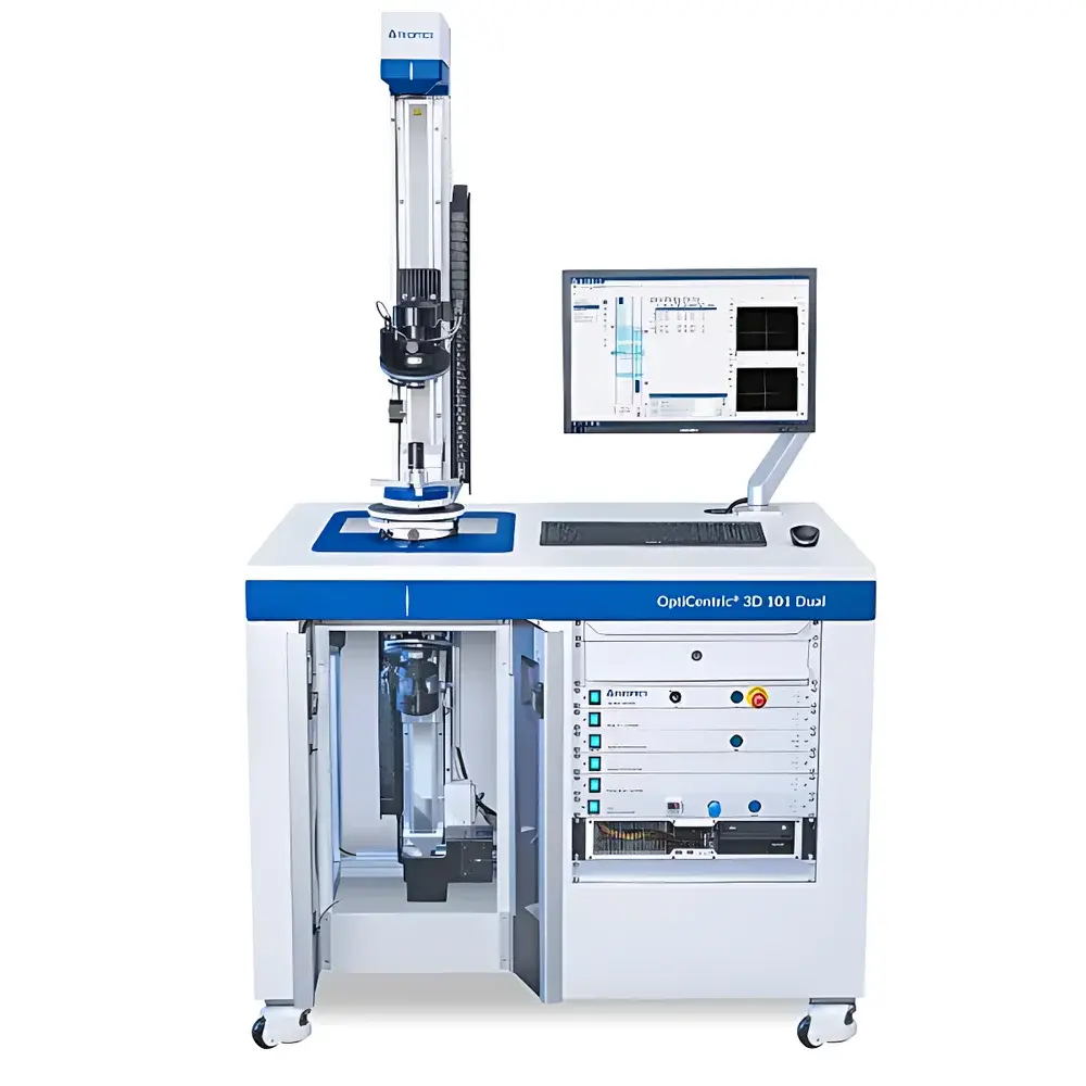
TRIOPTICS OptiCentric® Dual-Path Centration Error Measurement System
| Brand | TRIOPTICS |
|---|---|
| Origin | Germany |
| Model | OptiCentric® |
| Compliance | ISO 10110-5, ISO 10110-12 |
| Measurement Principle | Dual-beam autocollimation and image centroid analysis |
| Optical Configuration | Collimated dual-path interferometric alignment |
| Typical Repeatability | < 0.5 arcsec (standard configuration) |
| Software Platform | OptiCentric Control v6.x |
| Data Export Formats | CSV, XML, PDF, SPC-compatible |
| Regulatory Conformance | CE, RoHS, FDA 21 CFR Part 11–ready audit trail (optional), GLP/GMP-compliant reporting modules |
Overview
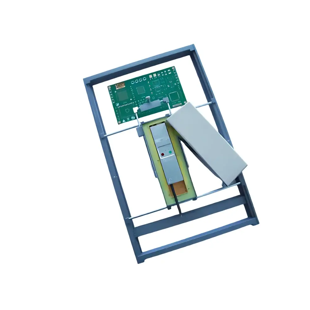
The TRIOPTICS OptiCentric® Dual-Path Centration Error Measurement System is a precision metrology platform engineered for quantitative assessment of optical centration error—defined as the angular misalignment between the mechanical axis (center of curvature or mounting surface) and the optical axis (chief ray path)—in individual lenses, cemented doublets, prisms, and complex optical assemblies. It operates on a dual-beam autocollimation principle: two independent collimated laser beams are directed symmetrically onto opposite surfaces of the test optic; deviations in reflected beam positions are captured by high-resolution CMOS sensors and processed via centroid detection algorithms to compute tilt and decenter vectors with sub-arcsecond resolution. This architecture eliminates reliance on single-point reflection assumptions and inherently compensates for thermal drift and mechanical hysteresis, delivering traceable, NIST-aligned measurements compliant with ISO 10110-5 (centration tolerances) and ISO 10110-12 (testing methods for centration). Designed for integration into cleanroom-based optical fabrication lines and R&D labs, the system supports both manual and fully automated workflows—including robotic sample loading—and is calibrated using certified reference standards traceable to PTB (Physikalisch-Technische Bundesanstalt).
Key Features
- Dual-path optical architecture enabling simultaneous measurement of front- and back-surface centration errors without repositioning or realignment
- Integrated motorized rotation stage with ≤ 0.001° angular resolution and absolute encoder feedback for full 360° azimuthal scanning
- Modular sensor head design accommodating visible (400–700 nm), NIR (700–1100 nm), and UV (266–355 nm) wavelengths via interchangeable laser sources and detectors
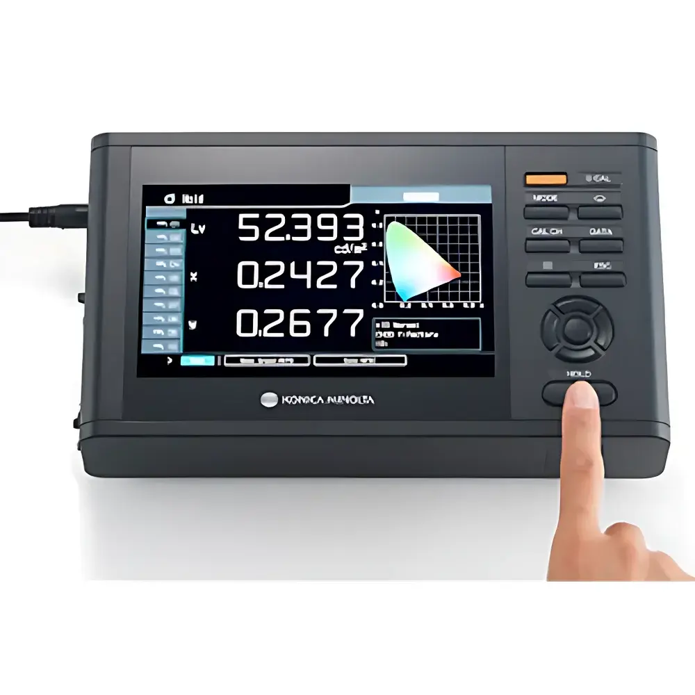
- Real-time deviation mapping with vectorial display of decenter (µm) and tilt (arcsec) components referenced to user-defined mechanical datums
- Automated edge-detection and surface-fit algorithms for non-spherical optics—including aspheres, cylindrical lenses, C-lenses, and reflective catadioptric systems (e.g., L- and U-shaped folded paths)
- Rugged granite base with active vibration isolation and temperature-stabilized optical bench (±0.1 °C stability over 8 h)
Sample Compatibility & Compliance
The OptiCentric® system accommodates optical components ranging from Ø3 mm micro-lenses to Ø300 mm telescope objectives, with thicknesses from 0.5 mm to 120 mm. It supports plano-convex, biconvex, meniscus, and aspheric singlets; cemented doublets and triplets; cylindrical and toroidal lenses; off-axis paraboloids; and multi-element folded systems such as Schmidt-Cassegrains and Ritchey-Chrétien configurations. All measurement protocols adhere to ISO 10110-5 Annex A (test procedures for centration) and support optional validation per ASTM E2912 (Standard Practice for Optical Component Centration Testing). The platform is routinely deployed in ISO 14644-1 Class 5 cleanrooms and meets IEC 61000-6-2/6-3 electromagnetic compatibility requirements. Calibration certificates include uncertainty budgets compliant with ISO/IEC 17025:2017.
Software & Data Management
OptiCentric Control v6.x provides a deterministic, deterministic GUI built on Qt framework with role-based access control (RBAC), electronic signature support, and configurable audit trails meeting FDA 21 CFR Part 11 requirements. Measurement sequences are scriptable via Python API (PyOptiCentric), enabling integration with MES, SAP QM, or LabVantage LIMS. Raw sensor data, intermediate centroid coordinates, fitted surface normals, and final error vectors are stored in hierarchical HDF5 containers with embedded metadata (wavelength, temperature, humidity, operator ID, calibration timestamp). Reports comply with ISO 9001 documentation standards and export to CSV (for SPC analysis), XML (for PLM integration), and PDF/A-2u (archival format). Batch processing mode enables statistical process control (SPC) charting across production lots, including Cp/Cpk calculation and trend analysis against user-defined specification limits.
Applications
- Quantitative verification of centration tolerances during lens grinding, polishing, and centering operations
- In-process inspection of cemented doublets prior to UV-curing to prevent stress-induced wavefront distortion
- Alignment verification of optical benches and optomechanical mounts in astronomical instrumentation
- Root-cause analysis of MTF degradation in imaging systems linked to element misalignment
- Validation of custom mount interfaces for freeform optics used in AR/VR waveguide combiners
- Calibration transfer between metrology stations in multi-site optical manufacturing networks
FAQ
What optical standards does the OptiCentric® system support?
It natively implements ISO 10110-5 (centration definition and tolerance specification), ISO 10110-12 (test methodology), and supports optional conformance to MIL-PRF-13830B and DIN EN ISO 10110 series parts 1–19.
Can it measure aspheric or freeform surfaces?
Yes—using adaptive surface-fitting algorithms that accept Zernike or XY polynomial coefficients imported from design files (Zemax .zmx, Code V .seq, or ASCII surface maps).
Is remote operation and monitoring supported?
Yes—via secure TLS-encrypted web interface (HTTPS) and OPC UA server for factory-wide SCADA integration.
Does the system require periodic recalibration by TRIOPTICS service engineers?
Annual calibration is recommended; however, built-in self-check routines (reference mirror drift monitoring, beam position stability logging) enable extended calibration intervals under controlled environmental conditions.
How is mechanical datum established for asymmetric or irregularly shaped optics?
Through configurable multi-point tactile probing (optional add-on) or vision-based fiducial recognition using integrated machine vision module (OptiVision™).