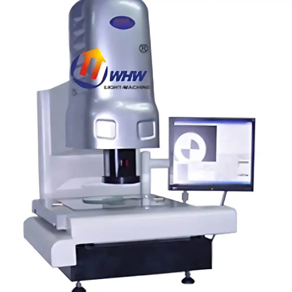
YANRUN YR-A4030 Automated Contact & Vision Coordinate Measuring Machine
| Brand | YANRUN |
|---|---|
| Origin | Shanghai, China |
| Manufacturer Type | Direct Manufacturer |
| Model | YR-A4030 |
| Operation Mode | Fully Automatic |
| Metal Table Size (mm) | 608 × 508 |
| Glass Table Size (mm) | 450 × 350 |
| Motion Travel (mm) | 400 × 300 |
| Overall Dimensions (mm) | 1022 × 743 × 1027 |
| Drive Mechanism | Ball Screw Driven by Stepper Motors on X/Y/Z Axes |
| Camera | SONY Color CCD Sensor |
| Positional Resolution (X/Y/Z) | 0.0005 mm |
| Coordinate Measurement Uncertainty | ≤ (3 + L/200) μm |
| Optical System | 0.7–4.5× Zoom Lens |
| Total Video Magnification | 30–190× (up to 380× with 2× Auxiliary Objective) |
| Illumination | Continuously Adjustable LED Ring Light (Surface & Profile) |
| Power Supply | AC 220 V ±10%, 50 Hz |
| Operating Environment | 20 °C ±3 °C, 45–75% RH |
Overview
The YANRUN YR-A4030 Automated Contact & Vision Coordinate Measuring Machine is a dual-mode metrology platform engineered for high-precision geometric inspection of mechanical components in quality control laboratories and production environments. It integrates non-contact optical measurement via high-resolution video microscopy with optional tactile probing—enabling comprehensive dimensional verification across planar and 3D features. The system operates on the principle of coordinate metrology: spatial coordinates of part features are captured either through edge-detection algorithms applied to live video feeds or via physical probe contact displacement sensing, then referenced to a calibrated machine coordinate system traceable to national standards. Designed for ISO/IEC 17025-compliant labs and manufacturing facilities adhering to IATF 16949 or AS9100, the YR-A4030 delivers repeatable sub-micron-level uncertainty performance under controlled environmental conditions (20 °C ±3 °C, 45–75% RH), satisfying foundational requirements for GD&T evaluation per ASME Y14.5 and ISO 1101.
Key Features
- Fully automated operation with programmable measurement routines, reducing operator dependency and inter-operator variability.
- Dual-stage optical path: motorized 0.7–4.5× zoom lens coupled with interchangeable auxiliary objectives (including 2×) enables total video magnification from 30× to 380×, supporting both macro-feature overview and fine-edge resolution.
- High-stability granite base and precision-ground metal table (608 mm × 508 mm) provide thermal and mechanical rigidity; optional glass stage (450 mm × 350 mm) facilitates backlight transmission for silhouette-based contour analysis.
- Ball screw-driven XYZ axes with stepper motor actuation ensure smooth, backlash-free motion and positional repeatability of ±0.0005 mm—critical for stitching multi-field-of-view measurements and maintaining traceability across large workpieces.
- Calibrated illumination system: independently controllable LED ring light modules deliver uniform surface illumination (for diffuse reflection) and sharp profile backlighting (for silhouette edge detection), dynamically optimized per magnification level.
- Integrated SONY color CCD camera with progressive scan capability captures high-fidelity image sequences suitable for edge gradient analysis, sub-pixel centroid calculation, and real-time autofocus-assisted focusing.
Sample Compatibility & Compliance
The YR-A4030 accommodates parts up to 400 mm × 300 mm in XY travel range and supports specimens with heights up to 200 mm (Z-axis clearance). It accepts metallic, ceramic, plastic, and composite materials—provided surface finish permits reliable edge contrast under configured lighting. The system complies with electromagnetic compatibility (EMC) requirements per GB/T 18268 (equivalent to IEC 61326-1) and meets safety standards under GB 4793.1 (IEC 61010-1). While not certified to ISO 10360 series out-of-the-box, its measurement uncertainty model (≤ (3 + L/200) μm) aligns with ISO 10360-2 for CMM verification when operated within specified environmental tolerances and following documented calibration procedures using certified step gauges and sphere artifacts.
Software & Data Management
The proprietary metrology software provides intuitive CAD-based alignment, auto-feature recognition (lines, circles, arcs, slots, polygons), and GD&T evaluation (position, concentricity, parallelism, perpendicularity, profile). All measurement programs support parameterized variables, loop structures, and conditional logic for adaptive inspection sequencing. Audit trails—including user ID, timestamp, instrument configuration, raw image capture, and result history—are retained locally with optional export to CSV, PDF, or XML formats. The software architecture supports 21 CFR Part 11 readiness through configurable electronic signatures, role-based access control, and immutable log files—facilitating GLP/GMP-aligned validation protocols in regulated industries such as medical device manufacturing and aerospace component supply chains.
Applications
- Verification of stamped sheet metal parts for hole position, slot width, and bend angle conformity.
- Dimensional release testing of injection-molded plastic housings, including wall thickness consistency and mating feature alignment.
- First-article inspection of machined aluminum or stainless-steel components per engineering drawings and PPAP documentation.
- Tooling validation for die sets and fixture plates where reference datum establishment and repeatability are critical.
- Failure analysis support—overlaying measured point clouds onto nominal CAD models to visualize deviation heatmaps and identify root causes of form error.
FAQ
Is the YR-A4030 compliant with ISO 10360-2 for CMM verification?
Yes—when operated under controlled environmental conditions and calibrated using traceable artifacts per manufacturer-recommended procedures, its stated uncertainty model satisfies the verification criteria outlined in ISO 10360-2 for medium-accuracy coordinate measuring machines.
Can the system perform true 3D measurements with tactile probing?
The YR-A4030 supports optional touch-trigger probe integration for Z-axis depth measurement and basic 3D feature acquisition (e.g., cylinder axis, sphere center); however, full 3D scanning functionality requires add-on probe modules and advanced software licensing.
What file formats does the software accept for CAD comparison?
Native support includes STEP AP203/AP214, IGES, DXF, and DWG; mesh-based STL files are supported for nominal surface comparison via deviation mapping.
Does the system require external air supply or vibration isolation?
No compressed air is required. While not mandatory, installation on a pneumatic isolation table is recommended for applications demanding ≤1 μm uncertainty at maximum travel range.
How often must the optical system be recalibrated?
Annual recalibration of the zoom lens magnification factor and camera pixel pitch is recommended; certificate traceability to NIM (National Institute of Metrology, China) or equivalent national metrology institute is available upon request.